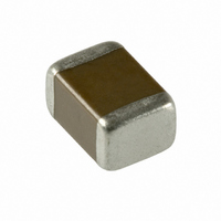
LMK432BJ226MM-T Taiyo Yuden, LMK432BJ226MM-T Datasheet

LMK432BJ226MM-T
Specifications of LMK432BJ226MM-T
CE LMK432 BJ226MM-T
Related parts for LMK432BJ226MM-T
LMK432BJ226MM-T Summary of contents
Page 1
... YLow equivalent series resistance(ESR) provides excellent noise absorp- tion characteristics. YCompared to tantalum or aluminum electrolytic capacitors these ceramic capacitors offer a number of excellent features, including: Higher permissible ripple current values Smaller case sizes relative to rated voltage Improved reliability due to higher insulation resistance and break- down voltage ...
Page 2
... A 6.8 685 10 106 A 22 226 47 476 100 107 220 227 ■低背積層セラミックコンデンサ Low profile Multilayer Ceramic Capacitors Cap Type 107 TC B/X5R X5R F/Y5V B/X7R VDC 10 6.3 6.3 4 6.3 ...
Page 3
... Low profile Multilayer Ceramic Capacitors アイテム一覧 PART NUMBERS (0603 case size) F107TYPE 定 格 形 名 ...
Page 4
PART NUMBERS (0603 case size) F212TYPE 定 格 形 名 電 圧 RatedVoltage Ordering code UMK21 23GD UMK21 33GD UMK21 73GG UMK21 83GG 50V UMK21 04GG UMK21 ...
Page 5
PART NUMBERS (0603 case size) F316TYPE 定 格 形 名 電 圧 RatedVoltage Ordering code UMK31 4GF 50V UMK31 4GL UMK31 4GL GMK31 4GL 35V GMK31 ...
Page 6
PART NUMBERS (0603 case size) F325TYPE 定 格 形 名 電 圧 RatedVoltage Ordering code UMK325 5GH 50V GMK325 5MN 35V TMK325 5MD TMK325 5MH TMK325 5MN ...
Page 7
... CHARACTERISTICS インピーダンスYESR–周波数特性例 Example of Impedance ESR vs. Frequency characteristics Y当社積層セラミックコンデンサ例 (Taiyo Yuden multilayer ceramic capacitor) LMK107F105Z ...
Page 8
CHARACTERISTICS JMK212BJ106M LMK432BJ226M TMK107 C105M LMK212BJ105K TMK316 C106M LMK212BJ225M 4 JMK432C107M 45 ...
Page 9
Minimum Quantity F袋づめ梱包 Bulk packaging 製品厚み 形式fEIAg Thickness Type mmfinchg 0.5 GMK105f0402g f0.020g GVK105f0402g 0.8 GMK107f0603g f0.031g 0.8 f0.031g G2K110f0504g 0.6 f0.024g 0.85 f0.033g GMK212f0805g 1.25 f0.049g 0.85 G4K212f0805g f0.033g 0.85 G2K212f0805g f0.033g 0.85 f0.033g 1.15 f0.045g GMK316f1206g ...
Page 10
Tape ( 8mm幅) f0.315inches wideg Type チップ挿入部 挿入ピッチ Chip Cavity Insertion Pitch Tape Thickness fEIAg A B 0.37M0.065 0.67M0.065 52.0M0.05 GMK063f0201g f0.06M0.002g f0.027M0.002g f0.079M0.002g f0.018max.g 0.65M0.15 1.15M0.15 52.0M0.05 GMK105f0402g GVK105f0402g f0.026M0.004g f0.045M0.004g f0.079M0.002g f0.031max.g 1.0M0.2 1.8M0.2 ...
Page 11
... RELIABILITY DATA Multilayer Ceramic Capacitor Chips Item Temperature Compensating (Class 1) Standard High Frequency Type 1.Operating Temperature K55 to J125C Range K55 to J125C Range 3.Rated Voltage 50VDC,25VDC, 16VDC 16VDC 50VDC 4.Withstanding Voltage No breakdown or dam- No abnormality Between terminals age 5.Insulation Resistance 10000 ME min. 6.Capacitance (Tolerance) ...
Page 12
... RELIABILITY DATA Multilayer Ceramic Capacitor Chips Item Temperature Compensating (Class 1) Standard High Frequency Type 10.Body Strength No mechanical dam- age. 11.Adhesion of Electrode No separation or indication of separation of electrode. 12.Solderability At least 95% of terminal electrode is covered by new solder. 13.Resistance to soldering Appearance: No abnor- Appearance: No abnor- mality mality ...
Page 13
... RELIABILITY DATA Multilayer Ceramic Capacitor Chips Item Temperature Compensating (Class 1) Standard High Frequency Type 16.Loading under Damp Heat Appearance: No abnor- Appearance: No abnor- mality mality Capacitance change: Capacitance change CT2 pF: Within M0.4 pF M0.75pF, whichever is CX2 pF: Within M0.75 larger CU30 pF: QU200 CD Nominal capaci- C< ...
Page 14
... PRECAUTIONS Precautions on the use of Multilayer Ceramic Capacitors Stages Precautions 1.Circuit Design Verification of operating environment, electrical rating and per- formance 1. A malfunction in medical equipment, spacecraft, nuclear re- actors, etc. may cause serious harm to human life or have severe social ramifications. As such, any capacitors to be ...
Page 15
... PRECAUTIONS Precautions on the use of Multilayer Ceramic Capacitors Stages Precautions 2.PCB Design Pattern configurations (Capacitor layout on panelized [breakaway] PC boards) 1. After capacitors have been mounted on the boards, chips can be subjected to mechanical stresses in subsequent manufac- turing processes (PCB cutting, board inspection, mounting of additional parts, assembly into the chassis, wave soldering the reflow soldered boards etc ...
Page 16
... PRECAUTIONS Precautions on the use of Multilayer Ceramic Capacitors Stages Precautions 3.Considerations for auto- Adjustment of mounting machine matic placement 1. Excessive impact load should not be imposed on the capaci- tors when mounting onto the PC boards. 2. The maintenance and inspection of the mounters should be conducted periodically. Selection of Adhesives 1 ...
Page 17
... Preheating when soldering Heating: Ceramic chip components should be preheated to within 100 to 130C of the sol- dering. Cooling: The temperature difference between the components and cleaning process should not be greater than 100C ...
Page 18
... Mechanical considerations 1. Be careful not to subject the capacitors to excessive mechani- cal shocks. (1)If ceramic capacitors are dropped onto the floor or a hard surface, they should not be used. (2)When handling the mounted boards, be careful that the mounted components do not come in contact with or bump against other boards or components ...
Page 19
... YCeramic chip capacitors should be kept where no chlorine or sulfur exists in the air. 2. The capacitance value of high dielectric constant capacitors (type 2 &3) will gradually decrease with the passage of time, so this should be taken into consideration in the circuit design ...


