1.5KE15A STMicroelectronics, 1.5KE15A Datasheet
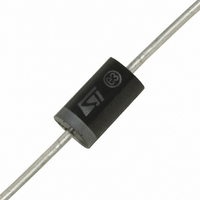
TRANSIL 1500W 15V UNIDIR DO-201

1.5KE15A

Manufacturer Part Number
1.5KE15A
Description
TRANSIL 1500W 15V UNIDIR DO-201
Manufacturer
STMicroelectronics
Series
TRANSIL™r
Datasheet

Specifications of 1.5KE15A

Voltage - Reverse Standoff (typ)
12.8V
Voltage - Breakdown
14.3V
Power (watts)
1500W
Polarization
Unidirectional
Mounting Type
Through Hole
Package / Case
DO-201AA, DO-27, Axial
Polarity
Unidirectional
Clamping Voltage
27.2 V
Operating Voltage
15 V
Breakdown Voltage
14.3 V
Termination Style
Through Hole
Peak Surge Current
1 mA
Peak Pulse Power Dissipation
1500 W
Capacitance
5000 pF
Maximum Operating Temperature
+ 175 C
Minimum Operating Temperature
- 65 C
Dimensions
0.189 in Dia. x 5.3 (Max) mm W x 0.374 in L x 5.3 (Max) mm H
Number Of Elements
1
Package Type
DO-201
Operating Temperature Classification
Military
Reverse Breakdown Voltage
14.3V
Reverse Stand-off Voltage
12.8V
Leakage Current (max)
1uA
Peak Pulse Current
368A
Test Current (it)
1mA
Operating Temp Range
-65C to 175C
Mounting
Through Hole
Pin Count
2
Lead Free Status / RoHS Status
Lead free / RoHS Compliant

Available stocks

Company
Part Number
Manufacturer
Quantity
Price
Part Number:
1.5KE15A
Manufacturer:
ST
0
Part Number:
1.5KE15A
Manufacturer:
VISHAY/威世
Quantity:
20 000
Part Number:
1.5KE15A-E3/54
Manufacturer:
VISHAY/威世
Quantity:
20 000
Company:
Part Number:
1.5KE15A-E3/54
Quantity:
70 000
Company:
Part Number:
1.5KE15A-E3/54
Quantity:
70 000
Part Number:
1.5KE15A-T
Manufacturer:
DIODES
Quantity:
4 288
Company:
Part Number:
1.5KE15A-T
Quantity:
900
Part Number:
1.5KE15ARL
Manufacturer:
ST
0
ABSOLUTE MAXIMUM RATINGS (T
Note 1 : For a surge greater than the maximum values, the diode will fail in short-circuit.
THERMAL RESISTANCES
DESCRIPTION
Transil diodes provide high overvoltage protection
by clamping action. Their instantaneous response
to transient overvoltages makes them particularly
suited to protect voltage sensitive devices such
as MOS Technology and low voltage supplied
IC’s.
FEATURES
February 2002- Ed: 3A
Symbol
Symbol
PEAK PULSE POWER : 1500 W (10/1000 s)
BREAKDOWN VOLTAGE RANGE :
From 6.8V to 440 V
UNI AND BIDIRECTIONAL TYPES
LOW CLAMPING FACTOR
FAST RESPONSE TIME
UL RECOGNIZED
R
R
I
P
T
th (j-a)
FSM
th (j-l)
T
T
P
stg
PP
L
j
®
Peak pulse power dissipation (see note 1)
Power dissipation on infinite heatsink
Non repetitive surge peak forward current
for unidirectional types
Storage temperature range
Maximum junction temperature
Maximum lead temperature for soldering during 10s at 5mm
from case
Junction to leads
Junction to ambient on printed circuit. L
amb
Parameter
Parameter
= 25°C)
lead
= 10 mm
Tj initial = T
T
tp = 10ms
Tj initial = T
amb
= 75°C
1.5KE6V8CA/440CA
amb
amb
1.5KE6V8A/440A
DO-201
- 65 to + 175
Value
Value
1500
200
175
230
20
75
TRANSIL
5
°C/W
Unit
Unit
C/W
°C
W
W
A
C
C
TM
1/6

Related parts for 1.5KE15A

1.5KE15A Summary of contents

Page 1

FEATURES PEAK PULSE POWER : 1500 W (10/1000 s) BREAKDOWN VOLTAGE RANGE : From 6.8V to 440 V UNI AND BIDIRECTIONAL TYPES LOW CLAMPING FACTOR FAST RESPONSE TIME UL RECOGNIZED DESCRIPTION Transil diodes provide high overvoltage protection by clamping ...

Page 2

... I Peak pulse current PP Voltage temperature coefficient T V Forward voltage drop F Types Unidirectional Bidirectional 1.5KE6V8A 1.5KE6V8CA 1.5KE7V5A 1.5KE7V5CA 1.5KE10A 1.5KE10CA 1.5KE12A 1.5KE12CA 1.5KE15A 1.5KE15CA 1.5KE18A 1.5KE18CA 1.5KE22A 1.5KE22CA 1.5KE24A 1.5KE24CA 1.5KE27A 1.5KE27CA 1.5KE30A 1.5KE30CA 1.5KE33A 1.5KE33CA 1.5KE36A 1.5KE36CA 1.5KE39A 1.5KE39CA 1.5KE47A 1.5KE47CA 1 ...

Page 3

Types Unidirectional Bidirectional 1.5KE200A 1.5KE200CA 1.5KE220A 1.5KE220CA 1.5KE250A 1.5KE250CA 1.5KE300A 1.5KE300CA 1.5KE350A 1.5KE350CA 1.5KE400A 1.5KE400CA 1.5KE440A 1.5KE440CA % 100 PULSE WAVEFORM 10/1000 1000 s Note 2 : Pulse test < 50 ...

Page 4

Fig Peak pulse power versus exponential pulse duration. Fig Clamping voltage versus peak pulse current. Exponential waveform: t Note : The curves of the figure 3 are specified for a junction temperature of 25°C before ...

Page 5

Fig Capacitance versus reverse applied voltage for unidirectional types (typical values). Fig Peak forward voltage drop versus peak forward current (typical values for unidirectional types). Note : Multiply by 2 for units with V BR > ...

Page 6

... No license is granted by implication or otherwise under any patent or patent rights of STMicroelectronics. Specifications mentioned in this publication are subject to change without notice. This publication supersedes and replaces all information previously supplied. ...

Related keywords