594D107X9025R2T Vishay, 594D107X9025R2T Datasheet
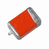
CAP TANT 100UF 25V 10% SMD

594D107X9025R2T

Manufacturer Part Number
594D107X9025R2T
Description
CAP TANT 100UF 25V 10% SMD
Manufacturer
Vishay
Series
TANTAMOUNT® 594Dr
Type
Conformal Coatedr
Datasheet

Specifications of 594D107X9025R2T

Esr
90mOhm
Capacitance
100µF
Voltage - Rated
25V
Tolerance
±10%
Esr (equivalent Series Resistance)
90.0 mOhm
Operating Temperature
-55°C ~ 125°C
Mounting Type
Surface Mount
Package / Case
2824 (7260 Metric)
Size / Dimension
0.283" L x 0.236" W (7.20mm x 6.00mm)
Height
0.138" (3.50mm)
Manufacturer Size Code
R
Features
General Purpose
Tolerance (+ Or -)
10%
Voltage
25VDC
Mounting Style
Surface Mount
Polarity
Polar
Construction
SMT Chip
Case Style
Conformal Coated
Case Code
R
Lead Spacing (nom)
Not Requiredmm
Df
8%
Dcl
25uA
Seal
Not Required
Insulation
Not Required
Failure Rate
Not Required
Wire Form
Not Required
Product Length (mm)
7.2mm
Product Height (mm)
3.5mm
Product Depth (mm)
6mm
Product Diameter (mm)
Not Requiredmm
Seated Plane Height
Not Requiredmm
Length W/weld (max)
Not Requiredmm
Operating Temp Range
-55C to 85C
Capacitor Application
Low ESR
Capacitance Tolerance
± 10%
Voltage Rating
25V
Capacitor Case Style
R
No. Of Pins
2
Operating Temperature Range
-55°C To +85°C
Svhc
No SVHC (15-Dec-2010)
Esr Frequency
100kHz
Rohs Compliant
Yes
Dimensions
6 mm W x 7.2 mm L
Mfr Case Code
R Case
Product
Tantalum Solid Low ESR Standard Grade
Termination Style
SMD/SMT
Lead Free Status / RoHS Status
Lead free / RoHS Compliant
Lead Spacing
-
Lead Free Status / Rohs Status
 Details

Available stocks

Company
Part Number
Manufacturer
Quantity
Price
Part Number:
594D107X9025R2T
Manufacturer:
VISHAY/威世
Quantity:
20 000
PERFORMANCE/ELECTRICAL CHARACTERISTICS
Operating Temperature: - 55 °C to + 85 °C
(To + 125 °C with voltage derating)
Note
• Refer to Doc. 40088
Capacitance Range: 1.0 µF to 1500 µF
Notes
• Preferred Tolerance and reel sizes are in bold.
• We reserve the right to supply higher voltage ratings and tighter capacitance tolerance capacitors in the same case size.
• Voltage substitutions will be marked with the higher voltage rating.
Notes
• The anode termination (D less B) will be a minimum of 0.012" [0.3 mm].
* Pb containing terminations are not RoHS compliant, exemptions may apply
Document Number: 40006
Revision: 11-May-09
CASE
CODE
TYPE
594D
ORDERING INFORMATION
DIMENSIONS in inches [millimeters]
C
D
R
B
picofarads. The first two
digits are the significant
figures. The third is the
T
This is expressed in
number of zeros to
ANTAMOUNT
L (MAX.)
CAPACITANCE
0.158
0.281
0.293
0.283
[4.0]
[7.1]
[7.5]
[7.2]
follow.
477
(MAX.)
L
(REF.)
D
0.110 + 0.012 - 0.016
0.170 + 0.012/- 0.024
0.235 + 0.012/- 0.024
[2.8 + 0.3 - 0.4]
[4.3 + 0.3/- 0.6]
[6.0 + 0.3/- 0.6]
0.126 ± 0.012
[3.2 ± 0.3]
CAPACITANCE
®
TOLERANCE
Solid Tantalum Chip Capacitors
X0 = ± 20 %
X9 = ± 10 %
W
, Conformal Coated, Maximum CV, Low ESR
X0
A
For technical questions, contact:
B
0.075 + 0.012 - 0.024
To complete the three-digit
point is indicated by an “R”
This is expressed in volts.
block, zeros precede the
voltage rating. A decimal
[1.9 + 0.3 - 0.6]
DC VOLTAGE RATING
0.098 ± 0.012
0.110 ± 0.012
0.136 ± 0.012
[2.5 ± 0.3]
[2.8 ± 0.3]
[3.5 ± 0.3]
(6R3 = 6.3 V).
AT + 85 °C
H
004
W
FEATURES
• Large capacitance rating range
• Lowest ESR for a surface mount tantalum chip
• Terminations: Tin (2) standard
• 8 mm, 12 mm tape and reel packaging
• Case code compatibility with EIA 535BAAC and
• Compliant to RoHS directive 2002/95/EC
Capacitance Tolerance: ± 10 %, ± 20 % standard
Voltage Rating: 4 WVDC to 50 WVDC
Equivalent Series Resistance: ESR readings measured at
100 kHz, + 25 °C from 3500 mΩ to 30 mΩ
0.031 ± 0.012
0.051 ± 0.012
0.051 ± 0.012
0.051 ± 0.012
tantalum@vishay.com
capacitor
available per EIA 481-1 and reeling per
IEC 286-3. 7" [178 mm] standard. 13" [330 mm]
available.
CECC30801 molded chips
[0.80 ± 0.30]
[1.3 ± 0.30]
[1.3 ± 0.30]
[1.3 ± .30]
CASE CODE
A
See Ratings
Codes Table
and Case
R
(MAX.)
0.097 ± 0.016
0.180 ± 0.024
0.180 ± 0.024
0.180 ± 0.024
J
[2.5 ± 0.4]
[4.6 ± 0.6]
[4.6 ± 0.6]
[4.6 ± 0.6]
TERMINATION
4 = Gold plated
2 = 100 % Tin
plated (60/40)
Special order
8 = Solder
B
H
2
(MAX.)
Tantalum Wire
Nib Identifies
Anode (+)
Terminal
J
D (REF.)
Vishay Sprague
0.138
0.236
0.253
0.243
[3.5]
[6.0]
[6.4]
[6.2]
W = 13" [330 mm] reel
T = Tape and reel
See tape and reel
specifications.
PACKAGING
7" [178 mm] reel
www.vishay.com
T
J (MAX.)
594D
0.004
0.004
0.004
0.004
[0.1]
[0.1]
[0.1]
[0.1]
85

Related parts for 594D107X9025R2T

594D107X9025R2T Summary of contents

Page 1

... For technical questions, contact: tantalum@vishay.com Vishay Sprague R 2 TERMINATION PACKAGING 2 = 100 % Tin T = Tape and reel and Case 4 = Gold plated 7" [178 mm] reel 8 = Solder W = 13" ...

Page 2

... Vishay Sprague RATINGS AND CASE CODES µ 1.0 1.5 2.2 3.3 4.7 6 100 B* 120 150 B/C 180 220 270 D 330 C* 390 470 C/R 560 680 D 1000 1500 R Note * Preliminary values, contact factory for availability STANDARD RATINGS CAPACITANCE CASE CODE (µF) ...

Page 3

... WVDC °C, 17 WVDC AT + 125 °C 594D335X_025B2T 0.8 594D106X_025B2T 2.5 594D156X_025C2T 3.8 594D226X_025C2T 5.5 594D336X_025D2T 8.3 594D476X_025D2T 11.8 For technical questions, contact: tantalum@vishay.com 594D ® Vishay Sprague MAX. DF MAX. ESR MAX. RIPPLE ° °C 100 kHz 100 kHz 120 Hz Irms Ω (%) ( 0.045 2 ...

Page 4

... Vishay Sprague STANDARD RATINGS CAPACITANCE CASE CODE (µ 100 R 2.2 B 4 1.0 B 4 Note * Preliminary values, contact factory for availability. For 10 % tolerance, specify “9”; for 20 % tolerance, change to “0”. TYPICAL CURVES °C, IMPEDANCE AND ESR VS. FREQUENCY "B" Case ...

Page 5

... Vishay disclaims any and all liability arising out of the use or application of any product described herein or of any information provided herein to the maximum extent permitted by law. The product specifications do not expand or otherwise modify Vishay’ ...

Related keywords