CTZ3E-30C-W1-AF AVX Corporation, CTZ3E-30C-W1-AF Datasheet
CTZ3E-30C-W1-AF
Specifications of CTZ3E-30C-W1-AF


Related parts for CTZ3E-30C-W1-AF


CTZ3E-30C-W1-AF Summary of contents
Page 1
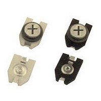
... Multilayer Ceramic Chip Trimmer Capacitors CTZ3 Series Four Basic Types: CTZ3S-P CTZ3-P CTZ3E-P CTZ3S-A CTZ3-A CTZ3E-A CTZ3S-P1.5 CTZ3-1.5 CTZ3E-P1.5 CTZ3S-PR CTZ3-PR CTZ3E-PR How To Order: CTZ3 E – – – Philips Adjustment Dimensions 0.1 3.2 0.1 0.9 0.01 0.78 0.1 1.1 1.7 0.1 Philips Adjust ...
Page 2
... Multilayer Ceramic Chip Trimmer Capacitors CTZ3 Series Specifications Type CTZ3-A (max. height=1.8mm, 1% setting drift) Part number Min. cap. value (pF) CTZ3 -03A 1.5 CTZ3 -05A 2 CTZ3 -05C 3 CTZ3 -10A 4 CTZ3 -10B 2 CTZ3 -10C 3 CTZ3 -20C 7.5 CTZ3 -30C 7.5 CTZ3 -40C 7.5 CTZ3 -50C 12 ...
Page 3
... Multilayer Ceramic Chip Trimmer Capacitors CTZ3-PR Series Conditions and Precautions Mounting Pattern: 1) Recommended pattern: 1.2 0.05 ø3.9 0.05 4.5 0.05 2) Determine if there is adequate room for mounting according to pattern dimensions and set pattern dimensions. 3) Connect stator terminal to voltage, rotor terminal to ground. 4) Make sure that the solder cream for coating is sufficient. (We recommend 150 m.) 5) Take caution that the solder flux and adhesive paste does not flow in between rotor and stator ...
Page 4
... Multilayer Ceramic Chip Trimmer Capacitors CTZ3-P/A/P1.5 Series Conditions and Precautions Mounting Pattern: 1) Recommended pattern: 0.5min. Rotor Lead (Ground) 0.5min. 2) Determine if there is adequate room for mounting according to pattern dimensions and set pattern dimensions. 3) Connect stator terminal to voltage, rotor terminal to ground. 4) Make sure that the solder cream for coating is sufficient. (We recommend 150 m.) 5) Take caution that the solder flux and adhesive paste does not flow in between rotor and stator ...
Page 5
... Multilayer Ceramic Chip Trimmer Capacitors CTZ2/CTZ3 Series Test Methods Item Humidity Test High Temperature Load Test Temperature Cycling Test Vibration Test Shock Resistance Test Solderability Resistance to Solder Heat Test Low Temperature Exposure Mechanical Load Setting Drift Recommended Washing Conditions Solvent AK225 ...
Page 6
Chip Trimmer Capacitor Packaging CTZ2 / CTZ3 Series Carrier Tape Dimensions SPROCKET HOLE CAVITY SEALED CONDITION DIRECTION OF FEED Reel ...
Page 7
Ceramic Tuning Tools For CTZ Series (21) 14 (21) 17 10.5 60 (x6) Acrylic Resin CTZ2 +0 2.2 -0.05 Ceramic 0.05 0.85 3 CTZ3 Ceramic 4.2 +0 0.03 0 2.2 -0.05 0.0 0.85 3 +0.04 ...