106-M2-P10-0.2A E-T-A, 106-M2-P10-0.2A Datasheet

CIRCUIT BREAKER PNL MT .2A 3PCS

106-M2-P10-0.2A

Manufacturer Part Number
106-M2-P10-0.2A
Description
CIRCUIT BREAKER PNL MT .2A 3PCS
Manufacturer
E-T-A
Series
106r
Datasheet

Specifications of 106-M2-P10-0.2A

Breaker Type
Thermal
Voltage
48VDC, 250VAC
Current - Trip (it)
200mA
Number Of Poles
1
Actuator Type
Push to Reset
Mounting Type
Panel Mount
Lead Free Status / RoHS Status
Lead free / RoHS Compliant
Other names
106-M2-P10-0.2AMP
1140-G111-P1M1-0.2A
302-1001
41-06-P10-0.2A
Miniaturised single pole thermal circuit breaker with push-to-reset,
tease- free, trip-free, snap action mechanism (R-type TO CBE to EN
60934). Available in versions for PCB or panel mounting, snap-in or
threadneck, or as an integral type. Manual release facility optional for
type 105.
Approved to CBE standard EN 60934 (IEC 60934). For higher current
ratings see type 1140.
Motors, transformers, solenoids, printed circuit boards, hand-held
machines and appliances, marine applications, caravans.
Type No.
104
105
106
106-M2
106
The exact part number required can be built up from the table of choices shown
above. Ordering references for optional features should be omitted if not required.
* mounting hardware bulk shipped
Current
rating (A)
0.05
0.08
0.1
0.2
0.3
0.4
0.5
0.6
0.7
0.8
1
1.2
1.5
Issue B
Description
Typical applications
Ordering information
Standard current ratings and typical internal resistance values
-
PCB mounting type (-PR), or integral type (-P30/P10)
snap-in panel mounting
threadneck panel mounting with hex and knurled nut*
threadneck panel mounting 3/8-27UNS with collar, hex nut and
knurled nut*
Terminal design
P10
P30
PR
PR2
PR3
P30 - .. - .. -
blade terminals A6.3-0.8 (QC .250)
blade terminals A2.8-0.8 (QC .110)
solder terminal pins for PCB mounting (type 104 only)
PCB mounting (vertical), type 104 only up to 6 A
PCB mounting (vertical), type 104 only
Shunt terminal (optional)
A3
Internal
resistance (Ω)
285
134
81
22
8.7
5.5
3.3
2.45
1.6
1.45
0.9
0.6
0.4
same as main terminals (up to I
Manual release facility (optional)
H
Thermal Overcurrent Circuit Breakers 104/105/106-...
only with type 105
Auxiliary contacts (optional)
Si51
..
- 5 A
type 104 only
Current ratings
0.05...10 A
Current
rating (A)
1.8
2
2.5
3
3.5
4
4.5
5
6
7
8
10
= ordering example
N
6 A/3 A max. load)
Internal
resistance (Ω)
0.28
0.25
0.18
0.11
0.076
0.067
0.051
≤ 0.05
≤ 0.05
≤ 0.05
≤ 0.05
≤ 0.05
www.e-t-a.com
Dielectric strength
(IEC 60664 and 60664A)
Degree of protection
Humidity
For further details please see chapter: Technical Information
Voltage rating
Current ratings
Auxiliary circuit
Typical life
Ambient temperature
Insulation co-ordination
(IEC 60664 and 60664 A)
Insulation resistance
Interrupting capacity I
Interrupting capacity
(UL 1077)
(IEC 60529/DIN 40050)
Vibration
Shock
Corrosion
Mass
Authority
VDE, SEV,
Kema (EN 60934)
CSA, UL
Circuit breakers with -Si51 not approved
Technical data
Approvals
AC 240 V
DC 48 V
operating area
104-...
0.05...8 A 2,000 operations at 1 x I
0.05...5 A 3,000 operations at 2 x I
6...8 A:
0.05...8 A 2,000 operations at 1 x I
0.05...5 A 3,000 operations at 2 x I
6...8 A:
10 A
10 A
cn
Voltage ratings
AC 240 V
DC 48 V
AC 250 V; DC 48 V
AC 240 V; DC 48 V
(UL: AC 250 V; DC 48 V)
0.05...10 A
0.5 A, AC 240 V, DC 28 V
500 operations at 2 x I
200 operations at 1 x I
50 operations at 2 x I
-20...+60 °C (-4...+140 °F) T 60
rated impulse
withstand voltage
2.5 kV
reinforced insulation in operating area
test voltage
AC 3,000 V
> 100 MΩ (DC 500 V)
0.05...8 A
> 8...10 A
0.05...10 A
I
0.05...10 A
0.05...10 A
operating area IP40
terminal area IP00
10 g (57-500 Hz) ± 0.76 mm (10-57 Hz),
to IEC 60068-2-6, test Fc,
10 frequency cycles/axis
25 g (11 ms) to IEC 60068-2-27, test Ea
96 hours at 5 % salt mist,
to IEC 60068-2-11, test Ka
240 hours at 95 % RH,
to IEC 60068-2-78, test Cab
approx. 10 g
N
105-...
6 x I
5 x I
6 x I
U
AC 250 V
DC 48 V
N
N
N
N
Current ratings
0.05...8 A
0.05...10 A
0.05...10 A
AC
AC
DC
N
N
N
N
, inductive
106-...
, inductive
, inductive
, inductive
pollution
degree
2
N
N
N
N
, inductive
, inductive
, inductive
, inductive
2,000 A
200 A
1 - 15
1

Related parts for 106-M2-P10-0.2A

106-M2-P10-0.2A Summary of contents

Page 1

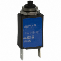
... Thermal Overcurrent Circuit Breakers 104/105/106-... Description Miniaturised single pole thermal circuit breaker with push-to-reset, tease- free, trip-free, snap action mechanism (R-type TO CBE to EN 60934). Available in versions for PCB or panel mounting, snap-in or threadneck integral type. Manual release facility optional for type 105. ...

Page 2

... Thermal Overcurrent Circuit Breakers 104/105/106-... 104-P30 ø7 .276 ø4 .157 1 blade terminals hole for DIN 46244-A2.8-0.8 mounting screw M2 (QC .110) usable depth 4.5 mm (.177 in.) 6.5 .256 9 .354 19 .748 104-P30 104-P30-A3 7...10 A 0.05...6 A 104-PR-(A3)-Si51 ø7 .276 ø4 .157 terminal design for ...

Page 3

... Thermal Overcurrent Circuit Breakers 104/105/106-... 104-PR2 ø7 0.05...6 A .276 ø4 .157 7 .276 0.8 15 .031 .591 6.5 hole for mounting .256 screw M2x5 9.1 .358 19.2 105-P30 .756 ø4 .157 .157 19 .748 blade terminals DIN 46244-A2.8-0.8 (QC .110) 12 .472 25 .984 inch mm inch ...

Page 4

... Thermal Overcurrent Circuit Breakers 104/105/106-... Installation drawings operating area 104-… 1 mounting area 8 .315 operating area 105-… 8 .315 mounting area 106-… operating area 8 mounting area .315 Accessories Water splash cover (transparent)/knurled nut assembly (type 106-... only) X 201 285 01 ...

Related keywords