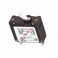
AA1-B0-34-615-3B1-C Carling Technologies, AA1-B0-34-615-3B1-C Datasheet

AA1-B0-34-615-3B1-C
Specifications of AA1-B0-34-615-3B1-C
Related parts for AA1-B0-34-615-3B1-C
AA1-B0-34-615-3B1-C Summary of contents
Page 1
A-Series – General Specifications Agency Certifications UL Recognized UL Standard 1077 Component Recognition Program as Protectors Supplementary (Guide CCN/QVNU2, File E75596) UL Standard 508 Switches, Industrial Control (Guide CCN/NRNT2, File E148683) UL Standard 1500 Protectors, Supplementary for Marine Electrical & ...
Page 2
Electrical Table A: Lists UL Recognized & CSA Accepted configurations and performance capabilities as a Component Supplementary Protector. Notes for Table A: 1 Requires branch circuit backup with a UL LISTED Type K5 or RK5 fuse (15A minimum ...
Page 3
... VAC, 125/250 VAC and 208Y/120 VAC Power Systems. 1 pole protector required for : 125 VAC, 1Ø Power System. Table D: Lists UL Listed configurations and performance capabilities as Circuit Breakers for use in Communications Equipment (Guide DITT, File E189195), under UL489A. ...
Page 4
... Mechanical Endurance 10,000 ON-OFF operations @ 6 per minute; with rated Current & Voltage. Trip Free All A-Series Circuit Breakers will trip on overload, even when the actuator is forcibly held in the ON position. Trip Indication The operating actuator moves posi- tively to the OFF position when an overload causes the circuit breaker to trip ...
Page 5
A-Series Handle UL Recognized – Ordering Scheme – Series Poles Actuator Circuit 1 SERIES A 2 ACTUATOR 1 A Handle, one per pole B Handle, one per multipole unit S Mid-Trip ...
Page 6
– Series Poles Aux/Alarm Actuator Circuit Switch 1 SERIES A 2 ACTUATOR 1 A Handle, one per pole S Mid-Trip Handle, one per pole T Mid-Trip Handle, one per pole ...
Page 7
A-Series Handle WORLD – Ordering Scheme – Series Poles Actuator Circuit 1 SERIES A 2 ACTUATOR 1 A Handle, one per pole S Mid-Trip Handle, one per pole T Mid-Trip Handle, ...
Page 8
Poles Series Actuator Circuit 1 SERIES A 2 ACTUATOR 1 M Sealed Toggle, one per unit 3 POLES 1 One 2 Two 3 Three 4 CIRCUIT ...
Page 9
A-Series Rocker UL Recognized – Ordering Scheme – Poles Series Actuator Circuit 1 SERIES A 2 ACTUATOR 1 Two Color Visi-Rocker Push-To-Reset , Single color C Indicate ON, vertical legend R ...
Page 10
Poles Aux/Alarm Series Actuator Circuit Switch 1 SERIES A 2 ACTUATOR 1 Two Color Visi-Rocker Push-To-Reset, Visi-Rocker C Indicate ON, vertical legend N D Indicate ON, horizontal legend F ...
Page 11
A-Series Flat Rocker UL Recognized – Ordering Scheme – Poles Series Actuator Circuit 1 SERIES A 2 ACTUATOR 1 Two Color Visi-Rocker 1 Indicate OFF, vertical legend 2 Indicate OFF, horizontal ...
Page 12
Poles Aux/Alarm Series Actuator Circuit Switch 1 SERIES A 2 ACTUATOR 1 Two Color Visi-Rocker 1 Indicate OFF, vertical legend 2 Indicate OFF, horizontal legend Single color 3 Vertical ...
Page 13
A-Series Handle – Circuit & Terminal Diagrams Notes: 1 All dimensions are in inches [millimeters]. 2 Tolerance ±.020 [.51] unless otherwise specified. 3 Alarm Switch available with .110 x .020 Q.C. & Solder Lug Terminals Only. 46 www.carlingtech.com ...
Page 14
Notes: 1 All dimensions are in inches [millimeters]. 2 Tolerance ±.020 [.51] unless otherwise specified. 3 Alarm Switch available with .110 x .020 QC & solder lug terminals only. www.carlingtech.com A-Series Handle – Circuit & Terminal Diagrams 47 ...
Page 15
A-Series Handle – Form & Fit Drawings Notes: 1 All dimensions are in inches [millimeters]. 2 Tolerance ± 0.20 [.51] unless otherwise specified. 3 For agency code P = .150 [3.81]. 48 www.carlingtech.com ...
Page 16
Notes: 1 All dimensions are in inches [millimeters]. 2 Recommended panel thickness: .040 [1.02] to .100 [2.54]. 3 Tolerance ±.020 [.51] unless otherwise specified. www.carlingtech.com A-Series Handle – Front Panel Snap-In Mounting Style 5 49 ...
Page 17
A-Series Handle – Front Panel Snap-In Mounting Style 7 Notes: 1 All dimensions are in inches [millimeters]. 2 Recommended panel thickness: .040 [1.02] to .100 [2.54]. 3 Tolerance ±.020 [.51] unless otherwise specified. 50 www.carlingtech.com ...
Page 18
Notes: 1 All dimensions are in inches [millimeters]. 2 Tolerance ±.020 [.51] unless otherwise specified. www.carlingtech.com A-Series Sealed Toggle – Form & Fit Drawings 51 ...
Page 19
A-Series Rocker – Circuit & Terminal Diagrams Notes: 1 All dimensions are in inches [millimeters]. 2 Tolerance ±.020 [.51] unless otherwise specified. 3 Schematic shown represents current trip circuit. 4. Circuits shown for >30 amps / VDE. 52 www.carlingtech.com ...
Page 20
Notes: 1 Dimensions apply to all variations shown. Notice that circuit breaker line & load terminal orientation on indicate OFF is opposite of indicate ON. 2 For pole orientation with horizontal legend, rotate front view clockwise 90°. 3 All dimensions ...
Page 21
A-Series Rocker Snap-In Bracket – Form & Fit Drawings Notes: 1 Dimensions apply to all variations shown. Notice that circuit breaker line & load terminal 2 For pole orientation with horizontal legend, rotate front view clockwise 90°. Orientation on indicate ...
Page 22
Notes: 1 All dimensions are in inches [millimeters]. 2 For pole orientation with horizontal legend, rotate front view clockwise 90°. 3 Tolerance ± 0.20 [.51] unless otherwise specified. www.carlingtech.com A-Series Flat Rocker – Form & Fit Drawings 55 ...
Page 23
A-Series PC Terminal Diagrams Notes: 1 Drawing illustrates A-Series with VDE certification. 2 All dimensions are in inches [millimeters]. 3 Tolerance ± 0.20 [.51] unless otherwise specified. 56 www.carlingtech.com ...


