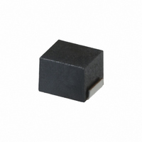
NLCV25T-220K-PF TDK Corporation, NLCV25T-220K-PF Datasheet - Page 2

NLCV25T-220K-PF
Manufacturer Part Number
NLCV25T-220K-PF
Description
INDUCTOR POWER 22UH 1008
Manufacturer
TDK Corporation
Series
NLCVr
Datasheet
1.NLCV25T-3R3M-PF.pdf
(2 pages)
Specifications of NLCV25T-220K-PF
Inductance
22µH
Tolerance
±10%
Package / Case
1008 (2520 Metric)
Current
160mA
Dc Resistance (dcr)
2.800 Ohm
Q @ Freq
30 @ 2.52MHz
Self Resonant Freq
18MHz
Mounting Type
Surface Mount
Operating Temperature
-40°C ~ 105°C
Frequency - Test
2.52MHz
Applications
Power Line
Test Frequency
2.52 MHz
Maximum Dc Current
160 mAmps
Maximum Dc Resistance
2.8 Ohms
Q Minimum
30
Dimensions
2 mm W x 2.5 mm L x 1.8 mm H
Operating Temperature Range
- 40 C to + 105 C
Termination Style
SMD/SMT
Lead Free Status / RoHS Status
Lead free / RoHS Compliant
Shielding
-
Current - Saturation
-
Current - Temperature Rise
-
Lead Free Status / Rohs Status
Lead free / RoHS Compliant
Other names
445-1758-2
NLCV25T-220K-PF
NLCV25T-220K-PF
Available stocks
Company
Part Number
Manufacturer
Quantity
Price
Part Number:
NLCV25T-220K-PF
Manufacturer:
TDK/东电化
Quantity:
20 000
Company:
Part Number:
NLCV25T-220K-PF
Manufacturer:
TDK
Quantity:
5 555
Company:
Part Number:
NLCV25T-220K-PFL
Manufacturer:
TDK
Quantity:
1 529
SHAPES AND DIMENSIONS/RECOMMENDED PC BOARD PATTERN
ELECTRICAL CHARACTERISTICS
Inductance(µH)
1
1.5
2.2
3.3
4.7
6.8
10
15
22
33
∗1
∗2
• Test equipment L, Q: HP4194A IMPEDANCE/GAIN PHASE ANALYZER+HP16085A+HP16093 B+TF-1
TYPICAL ELECTRICAL CHARACTERISTICS
INDUCTANCE CHANGE vs. DC SUPERPOSITION
CHARACTERISTICS
• All specifications are subject to change without notice.
Terminal
electrode
100
Rated current: Value obtained when current flows and the temperature has risen to 20°C or when DC current flows and the initial value of inductance has
fallen by 10%, whichever is smaller.
0.3
0.1
30
10
3
1
: Please specify lead-free compatible product, PF (Conformity to RoHS directive, exemption regulations apply) or EF (Conformity to RoHS directive)
10
30
2.5±0.2
( 0.4 )
SRF: HP8753C NETWORK ANALYZER
Rdc: MATSUSHITA VP-2941A DIGITAL MILLIOHM METER
100
Inductance
tolerance
±20%
±20%
±20%
±20%
±20%
±20%
±10%
±10%
±10%
±10%
1µH
22µH
10µH
4.7µH
2.2µH
DC current ( mA )
300
1000
2±0.1
Q
ref.
20
20
20
20
20
20
30
30
30
30
3000
1.4±0.1
10000
Test frequency L,Q
(MHz)
7.96
7.96
7.96
7.96
7.96
7.96
2.52
2.52
2.52
2.52
Weight:25mg
Self-resonant
frequency
(MHz)min.
200
165
95
55
43
39
32
21
18
16
1.0
IMPEDANCE vs. FREQUENCY CHARACTERISTICS
1.5
100
0.3
0.1
30
10
3
1
1
1.0
Inductor
Solder land pattern
3
DC resistance
(Ω)±30%
0.34
0.42
0.5
0.65
0.8
1
1.69
2.2
2.8
4.2
Dimensions in mm
10
Frequency ( MHz )
30
22µH
10µH
4.7µH
100
Rated current
(mA)max.
475
435
390
340
285
275
210
175
160
120
2.2µH
300
002-08 / 20080708 / e531_nlcv25.fm
1µH
1000
∗1
Part No.
NLCV25T-1R0M-
NLCV25T-1R5M-
NLCV25T-2R2M-
NLCV25T-3R3M-
NLCV25T-4R7M-
NLCV25T-6R8M-
NLCV25T-100K-
NLCV25T-150K-
NLCV25T-220K-
NLCV25T-330K-
(2/2)
∗2


