VLF3012AT-3R3MR87 TDK Corporation, VLF3012AT-3R3MR87 Datasheet
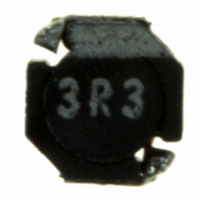
INDUCTOR POWER 3.3UH .87A SMD

VLF3012AT-3R3MR87

Manufacturer Part Number
VLF3012AT-3R3MR87
Description
INDUCTOR POWER 3.3UH .87A SMD
Manufacturer
TDK Corporation
Series
VLFr

Specifications of VLF3012AT-3R3MR87

Inductance
3.3µH
Tolerance
±20%
Shielding
Shielded
Current
870mA
Current - Temperature Rise
1.2A
Dc Resistance (dcr)
130 mOhm Max
Package / Case
0.110" L x 0.102" W x 0.047" H (2.80mm x 2.60mm x 1.20mm)
Mounting Type
Surface Mount
Operating Temperature
-40°C ~ 105°C
Frequency - Test
100kHz
Applications
Power Line
Product
Inductors
Test Frequency
100 KHz
Maximum Dc Current
0.87 Amp
Maximum Dc Resistance
0.13 Ohms
Dimensions
2.8 mm W x 2.6 mm L x 1.2 mm H
Operating Temperature Range
- 40 C to + 105 C
Termination Style
SMD/SMT
Lead Free Status / RoHS Status
Lead free / RoHS Compliant
Q @ Freq
-
Self Resonant Freq
-
Current - Saturation
-
Lead Free Status / Rohs Status
Lead free / RoHS Compliant
Other names
445-3224-2

Available stocks

Company
Part Number
Manufacturer
Quantity
Price
Part Number:
VLF3012AT-3R3MR87
Manufacturer:
TDK
Quantity:
220 000
Part Number:
VLF3012AT-3R3MR87
Manufacturer:
TDK/东电化
Quantity:
20 000
Part Number:
VLF3012AT-3R3MR87
Manufacturer:
TDK
Quantity:
4 832
Inductors
For Power Line
SMD
FEATURES
• Miniature size
• Generic use for portable DC to DC converter line
• High magnetic shield construction should actualize high resolu-
• Available for automatic mounting in tape and real package.
• The products do not contain lead and support lead-free solder-
APPLICATIONS
DVCs, DSCs, PDAs, LCD displays, Cellular phones, HDDs, etc.
ELECTRICAL CHARACTERISTICS
Part No.
VLF3012AT-1R5N1R2
VLF3012AT-2R2M1R0
VLF3012AT-3R3MR87
VLF3012AT-4R7MR74
VLF3012AT-6R8MR59
VLF3012AT-100MR49
VLF3012AT-150MR41
VLF3012AT-220MR33
VLF3012AT-330MR27
VLF3012AT-470MR22
• Operating temperature range: –40 to +105°C (Including self-temperature rise)
TYPICAL ELECTRICAL CHARACTERISTICS
INDUCTANCE vs. DC SUPERPOSITION CHARACTERISTICS
VLF3012AT-1R5N1R2
• All specifications are subject to change without notice.
Rated current: Value obtained when current flows and the temperature has risen to 40°C or when DC current flows and the nominal value of inductance
has fallen by 30%, whichever is smaller.
Mount area: 2.6
Low profile: 1.2mm max. height
tion for EMC protection.
ing.
2.5
2.0
1.5
1.0
0.5
0.0
0.0
0.2
×
0.4
2.8mm
DC current ( A )
0.6
Inductance
(µH)
1.5
2.2
3.3
4.7
6.8
10
15
22
33
47
0.8
1.0
Inductance
tolerance(%)
±30
±20
±20
±20
±20
±20
±20
±20
±20
±20
1.2
1.4
Test frequency
(kHz)
100
100
100
100
100
100
100
100
100
100
VLF Series VLF3012A Type
SHAPES AND DIMENSIONS
RECOMMENDED PC BOARD PATTERN
VLF3012AT-2R2M1R0
2.8±0.2
DC resistance(
max.
0.068
0.1
0.13
0.19
0.27
0.41
0.62
0.76
1.3
2.2
3.0
2.5
2.0
1.5
1.0
0.5
0.0
2.1
3.4
0.0
0.2
typ.
0.059
0.088
0.11
0.16
0.23
0.36
0.54
0.66
1.1
1.9
Dimensions in mm
)
0.4
1.2max.
( Include terminal area )
1.0
0.74
0.59
0.49
0.41
0.33
Rated current(A)
Based on inductance
change max.
1.2
0.87
0.27
0.22
DC current ( A )
0.6
Dimensions in mm
0.8
001-03 / 20050904 / e531_vlf3012a.fm
1.0
1.2
Based on temperature
rise typ.
1.6
1.3
1.2
0.98
0.83
0.67
0.54
0.49
0.38
0.29
1.4
(1/2)

Related parts for VLF3012AT-3R3MR87

VLF3012AT-3R3MR87 Summary of contents

Page 1

... Available for automatic mounting in tape and real package. • The products do not contain lead and support lead-free solder- ing. APPLICATIONS DVCs, DSCs, PDAs, LCD displays, Cellular phones, HDDs, etc. ELECTRICAL CHARACTERISTICS Inductance Part No. (µH) VLF3012AT-1R5N1R2 1.5 VLF3012AT-2R2M1R0 2.2 VLF3012AT-3R3MR87 3.3 VLF3012AT-4R7MR74 4.7 VLF3012AT-6R8MR59 6.8 VLF3012AT-100MR49 10 VLF3012AT-150MR41 15 VLF3012AT-220MR33 22 VLF3012AT-330MR27 ...

Page 2

... Inductors For Power Line SMD TYPICAL ELECTRICAL CHARACTERISTICS INDUCTANCE vs. DC SUPERPOSITION CHARACTERISTICS VLF3012AT-3R3MR87 0.0 0.2 0.4 0.6 0.8 DC current ( A ) VLF3012AT-6R8MR59 0.0 0.1 0.2 0.3 0.4 0.5 DC current ( A ) VLF3012AT-150MR41 0.0 0.1 0.2 0.3 0.4 DC current ( A ) VLF3012AT-330MR27 0.0 0.1 0.2 DC current ( A ) TEST CIRCUIT C=20,000µ ...

Related keywords