PM2120-681K JW Miller A Bourns Company, PM2120-681K Datasheet
PM2120-681K
Manufacturer Part Number
PM2120-681K
Description
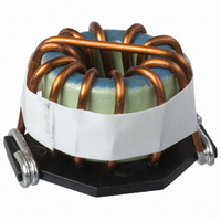
INDUCTOR TOROID 680UH 10% SMD
Manufacturer
JW Miller A Bourns Company
Series
PM2120r
Type
Toroidalr
Datasheet
1.PM2120-820K-RC.pdf
(2 pages)
Specifications of PM2120-681K
Inductance
680µH
Current
3A
Tolerance
±10%
Dc Resistance (dcr)
142 mOhm Max
Package / Case
1.200" L x 1.000" W x 0.850" H (30.50mm x 25.40mm x 21.59mm)
Mounting Type
Surface Mount
Operating Temperature
-55°C ~ 105°C
Frequency - Test
1kHz
Material - Core
Iron
Applications
Power Supplies
Lead Free Status / RoHS Status
Contains lead / RoHS non-compliant
Shielding
-
Q @ Freq
-
Self Resonant Freq
-
Current - Saturation
-
Current - Temperature Rise
-
Other names
M6205


*RoHS Directive 2002/95/EC Jan 27 2003 including Annex.
Specifi cations are subject to change without notice.
Customers should verify actual device performance in their specifi c applications.
Bourns Part No.
PM2120-1R0M-RC
PM2120-1R2M-RC
PM2120-1R5M-RC
PM2120-1R8M-RC
PM2120-2R2M-RC
PM2120-2R7M-RC
PM2120-3R3M-RC
PM2120-3R9M-RC
PM2120-4R7M-RC
PM2120-5R6M-RC
PM2120-6R8M-RC
PM2120-8R2M-RC
PM2120-100K-RC
PM2120-120K-RC
PM2120-150K-RC
PM2120-180K-RC
PM2120-220K-RC
PM2120-270K-RC
PM2120-330K-RC
PM2120-390K-RC
PM2120-470K-RC
PM2120-560K-RC
PM2120-680K-RC
PM2120-820K-RC
PM2120-101K-RC
PM2120-121K-RC
PM2120-151K-RC
PM2120-181K-RC
PM2120-221K-RC
PM2120-271K-RC
PM2120-331K-RC
PM2120-391K-RC
PM2120-471K-RC
PM2120-561K-RC
PM2120-681K-RC
PM2120-821K-RC
PM2120-102K-RC
Electrical Specifi cations
Electrical Schematic
1000
(μH)
Inductance 1 kHz
100
120
150
180
220
270
330
390
470
560
680
820
1.0
1.2
1.5
1.8
2.2
2.7
3.3
3.9
4.7
5.6
6.8
8.2
10
12
15
18
22
27
33
39
47
56
68
82
Tol. (%)
±20
±20
±20
±20
±20
±20
±20
±20
±20
±20
±20
±20
±10
±10
±10
±10
±10
±10
±10
±10
±10
±10
±10
±10
±10
±10
±10
±10
±10
±10
±10
±10
±10
±10
±10
±10
±10
Features
■
■
■
■
PM2120 Series - High Current SMD Power Inductors
Typical Part Marking
Formerly
Current rating up to 25.4 A
Toroidal core
RoHS compliant*
DCR
Max.
(mΩ)
100
108
119
130
142
157
215
11
12
13
14
19
21
29
32
35
39
43
47
52
72
2
2
3
3
3
3
4
4
5
5
6
6
7
8
9
9
J. W .Miller
PM2120-xxxx-RC
25.4
25.4
22.0
22.0
19.7
19.7
18.0
18.0
16.6
15.6
14.7
14.7
13.9
12.7
12.2
11.8
11.0
10.4
10.1
Idc
(A)
9.6
8.2
7.9
6.7
6.4
6.1
5.8
5.5
5.3
5.0
4.2
3.6
3.5
3.3
3.2
3.0
2.9
2.5
model
20.83 / (0.82)
20.83 / (0.82)
20.83 / (0.82)
20.83 / (0.82)
20.83 / (0.82)
20.83 / (0.82)
20.83 / (0.82)
20.83 / (0.82)
20.83 / (0.82)
20.83 / (0.82)
20.83 / (0.82)
20.83 / (0.82)
20.83 / (0.82)
20.83 / (0.82)
20.83 / (0.82)
20.83 / (0.82)
20.83 / (0.82)
20.83 / (0.82)
20.83 / (0.82)
20.83 / (0.82)
20.07 / (0.79)
20.07 / (0.79)
19.56 / (0.77)
20.10 / (0.87)
20.10 / (0.87)
20.10 / (0.87)
20.10 / (0.87)
21.08 / (0.83)
21.08 / (0.83)
20.32 / (0.80)
19.81 / (0.78)
19.81 / (0.78)
21.59 / (0.85)
21.59 / (0.85)
21.59 / (0.85)
21.59 / (0.85)
20.83 / (0.82)
mm/(in.)
Dim. A
Max.
Applications
■
■
■
Test Voltage .................................... 0.1 V
Refl ow Soldering .......245 °C; 5 seconds
Operating Temperature
Storage Temperature .. -55 °C to +105 °C
Resistance to Soldering Heat
Core .................................................. Iron
Wire ............................ Enameled copper
Adhesive ...............................Epoxy resin
Terminal ...................................Sn/Ag/Cu
Rated Current
Temperature Rise
Packaging ...................... 77 pcs. per box
General Specifi cations
Materials
Product Dimensions
Recommended Pad Layout
Input/output of DC/DC converters
Industrial electronics
Power supplies for:
• Portable communications equipment
• Camcorders
• LCD TVs
• Car radios
............................... -55 °C to +105 °C
...........................260 °C, 10 sec. max.
.....See “Inductance vs. Current” table
..............................30 °C typical at Idc
DIMENSIONS:
(1.200 ± .0200)
(Temperature rise included)
30.5 ± 0.5
(0.200)
5.1
(0.900)
22.9
(INCHES)
MM
(1.000)
MAX.
25.4
A
(0.700)
17.8
Related parts for PM2120-681K
Image
Part Number
Description
Manufacturer
Datasheet
Request
R

Part Number:
Description:
INDUCTOR TOROID 82UH 10% SMD
Manufacturer:
JW Miller A Bourns Company
Datasheet:
Part Number:
Description:
INDUCTOR TOROID 22UH 10% SMD
Manufacturer:
JW Miller A Bourns Company
Datasheet:
Part Number:
Description:
INDUCTOR TOROID 33UH 10% SMD
Manufacturer:
JW Miller A Bourns Company
Datasheet:
Part Number:
Description:
INDUCTOR TOROID 47UH 10% SMD
Manufacturer:
JW Miller A Bourns Company
Datasheet:
Part Number:
Description:
INDUCTOR TOROID 10UH 10% SMD
Manufacturer:
JW Miller A Bourns Company
Datasheet:
Part Number:
Description:
INDUCTOR TOROID 68UH 10% SMD
Manufacturer:
JW Miller A Bourns Company
Datasheet:
Part Number:
Description:
INDUCTOR TOROID 220UH 10% SMD
Manufacturer:
JW Miller A Bourns Company
Datasheet:
Part Number:
Description:
INDUCTOR TOROID 150UH 10% SMD
Manufacturer:
JW Miller A Bourns Company
Datasheet:
Part Number:
Description:
INDUCTOR TOROID 18UH 10% SMD
Manufacturer:
JW Miller A Bourns Company
Datasheet:
Part Number:
Description:
INDUCTOR TOROID 27UH 10% SMD
Manufacturer:
JW Miller A Bourns Company
Datasheet:

Part Number:
Description:
CHOKE COMMON MODE 1mH 4.8A
Manufacturer:
JW Miller A Bourns Company
Datasheet:

Part Number:
Description:
INDUCTOR EMI COM MODE 0.6MH 15%
Manufacturer:
JW Miller A Bourns Company
Datasheet:
Part Number:
Description:
INDUCTOR EMI COMMON MODE 2mH 15%
Manufacturer:
JW Miller A Bourns Company
Datasheet:
Part Number:
Description:
INDUCTOR EMI COMMON MODE 3mH 15%
Manufacturer:
JW Miller A Bourns Company
Datasheet:
Part Number:
Description:
INDUCTOR TOROID DUAL 6.0UH 15%
Manufacturer:
JW Miller A Bourns Company
Datasheet:
PM2120-681K Summary of contents
Page 1
... PM2120-331K-RC 330 ±10 PM2120-391K-RC 390 ±10 PM2120-471K-RC 470 ±10 PM2120-561K-RC 560 ±10 PM2120-681K-RC 680 ±10 PM2120-821K-RC 820 ±10 PM2120-102K-RC 1000 ±10 Electrical Schematic *RoHS Directive 2002/95/EC Jan 27 2003 including Annex. Specifi cations are subject to change without notice. Customers should verify actual device performance in their specifi c applications. ...
Page 2
... PM2120 Series - High Current SMD Power Inductors Inductance vs. Current Idc (A) Idc (A) L (μH) to decrease L to decrease 15.3 24.5 1.2 17.4 27.9 1.5 15.8 25.3 1.8 14.6 23.4 2.2 13.1 21.0 2.7 11.7 18.7 3.3 15.1 24.2 3.9 9.70 15.5 4.7 8.90 14 ...