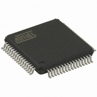
AT89C51ED2-RDTUM Atmel, AT89C51ED2-RDTUM Datasheet - Page 104

AT89C51ED2-RDTUM
Manufacturer Part Number
AT89C51ED2-RDTUM
Description
IC 8051 MCU FLASH 64K 64VQFP
Manufacturer
Atmel
Series
89Cr
Datasheet
1.ATWEBDVK-02RC.pdf
(137 pages)
Specifications of AT89C51ED2-RDTUM
Core Processor
8051
Core Size
8-Bit
Speed
60MHz
Connectivity
SPI, UART/USART
Peripherals
POR, PWM, WDT
Number Of I /o
50
Program Memory Size
64KB (64K x 8)
Program Memory Type
FLASH
Eeprom Size
2K x 8
Ram Size
2K x 8
Voltage - Supply (vcc/vdd)
2.7 V ~ 5.5 V
Oscillator Type
External
Operating Temperature
-40°C ~ 85°C
Package / Case
64-TQFP, 64-VQFP
Processor Series
AT89x
Core
8051
Data Bus Width
8 bit
Data Ram Size
2 KB
Interface Type
UART, SPI
Maximum Clock Frequency
60 MHz
Number Of Programmable I/os
50
Number Of Timers
3
Operating Supply Voltage
2.7 V to 5.5 V
Maximum Operating Temperature
+ 85 C
Mounting Style
SMD/SMT
3rd Party Development Tools
PK51, CA51, A51, ULINK2
Minimum Operating Temperature
- 40 C
Cpu Family
AT89
Device Core
8051
Device Core Size
8b
Frequency (max)
40MHz
Total Internal Ram Size
2KB
# I/os (max)
50
Number Of Timers - General Purpose
3
Operating Supply Voltage (typ)
3.3/5V
Operating Supply Voltage (max)
5.5V
Operating Supply Voltage (min)
2.7V
Instruction Set Architecture
CISC
Operating Temp Range
-40C to 85C
Operating Temperature Classification
Industrial
Mounting
Surface Mount
Pin Count
64
Package Type
VQFP
For Use With
AT89OCD-01 - USB EMULATOR FOR AT8XC51 MCU
Lead Free Status / RoHS Status
Lead free / RoHS Compliant
Data Converters
-
Lead Free Status / Rohs Status
Details
Available stocks
Company
Part Number
Manufacturer
Quantity
Price
Company:
Part Number:
AT89C51ED2-RDTUM
Manufacturer:
ATMEL
Quantity:
19 090
Part Number:
AT89C51ED2-RDTUM
Manufacturer:
MICROCHIP/微芯
Quantity:
20 000
24.8.3
24.9
24.9.1
24.9.2
24.9.3
104
Flow Description
AT89C51RD2/ED2
Checksum Error
Overview
Communication Initialization
Autobaud Performances
The Full Chip Erase does not affect the bootloader.
When a checksum error is detected, send ‘X’ followed with CR&LF.
An initialization step must be performed after each Reset. After microcontroller reset, the boot-
loader waits for an autobaud sequence (see section ‘Autobaud Performances’).
When the communication is initialized, the protocol depends on the record type requested by the
host.
FLIP, a software utility to implement ISP programming with a PC, is available from the Atmel
web site.
The host initializes the communication by sending a ’U’ character to help the bootloader to com-
pute the baudrate (autobaud).
Figure 24-7. Initialization
The ISP feature allows a wide range of baud rates in the user application. It is also adaptable to
a wide range of oscillator frequencies. This is accomplished by measuring the bit-time of a single
bit in a received character. This information is then used to program the baud rate in terms of
timer counts based on the oscillator frequency. The ISP feature requires that an initial character
(an uppercase U) be sent to the AT89C51RD2/ED2 to establish the baud rate. Table show the
autobaud capability.
Table 24-8.
Frequency
(MHz)
Baudrate (kHz)
2400
• SBV = FCh
• SSB = FFh
Autobaud Performances
Communication Opened
Init Communication
Else
If (Not Received "U")
1.8432
Host
OK
OK
2
2.4576
OK
OK
3
"U"
3.6864
"U"
OK
OK
4
Performs Autobaud
Sends Back “U” Character
OK
5
Bootloader
OK
4235K–8051–05/08
6
7.3728
OK


