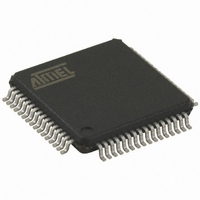
AT89C51ED2-RDTUM Atmel, AT89C51ED2-RDTUM Datasheet - Page 112

AT89C51ED2-RDTUM
Manufacturer Part Number
AT89C51ED2-RDTUM
Description
IC 8051 MCU FLASH 64K 64VQFP
Manufacturer
Atmel
Series
89Cr
Datasheet
1.ATWEBDVK-02RC.pdf
(137 pages)
Specifications of AT89C51ED2-RDTUM
Core Processor
8051
Core Size
8-Bit
Speed
60MHz
Connectivity
SPI, UART/USART
Peripherals
POR, PWM, WDT
Number Of I /o
50
Program Memory Size
64KB (64K x 8)
Program Memory Type
FLASH
Eeprom Size
2K x 8
Ram Size
2K x 8
Voltage - Supply (vcc/vdd)
2.7 V ~ 5.5 V
Oscillator Type
External
Operating Temperature
-40°C ~ 85°C
Package / Case
64-TQFP, 64-VQFP
Processor Series
AT89x
Core
8051
Data Bus Width
8 bit
Data Ram Size
2 KB
Interface Type
UART, SPI
Maximum Clock Frequency
60 MHz
Number Of Programmable I/os
50
Number Of Timers
3
Operating Supply Voltage
2.7 V to 5.5 V
Maximum Operating Temperature
+ 85 C
Mounting Style
SMD/SMT
3rd Party Development Tools
PK51, CA51, A51, ULINK2
Minimum Operating Temperature
- 40 C
Cpu Family
AT89
Device Core
8051
Device Core Size
8b
Frequency (max)
40MHz
Total Internal Ram Size
2KB
# I/os (max)
50
Number Of Timers - General Purpose
3
Operating Supply Voltage (typ)
3.3/5V
Operating Supply Voltage (max)
5.5V
Operating Supply Voltage (min)
2.7V
Instruction Set Architecture
CISC
Operating Temp Range
-40C to 85C
Operating Temperature Classification
Industrial
Mounting
Surface Mount
Pin Count
64
Package Type
VQFP
For Use With
AT89OCD-01 - USB EMULATOR FOR AT8XC51 MCU
Lead Free Status / RoHS Status
Lead free / RoHS Compliant
Data Converters
-
Lead Free Status / Rohs Status
Details
Available stocks
Company
Part Number
Manufacturer
Quantity
Price
Company:
Part Number:
AT89C51ED2-RDTUM
Manufacturer:
ATMEL
Quantity:
19 090
Part Number:
AT89C51ED2-RDTUM
Manufacturer:
MICROCHIP/微芯
Quantity:
20 000
24.10 API Call Description
24.10.1
24.10.2
Table 24-10. API Call Summary
112
PROGRAM DATA BYTE
READ DEVICE ID1
READ DEVICE ID2
READ DEVICE ID3
READ MANUF ID
ERASE BLOCK
Command
AT89C51RD2/ED2
Process
Constraints
00h
00h
00h
00h
01h
02h
R1
The IAP allows to reprogram a microcontroller on-chip Flash memory without removing it from
the system and while the embedded application is running.
The user application can call some Application Programming Interface (API) routines allowing
IAP. These API are executed by the bootloader.
To call the corresponding API, the user must use a set of Flash_api routines which can be linked
with the application.
Example of Flash_api routines are available on the Atmel web site on the software application
note:
C Flash Drivers for the AT89C51RD2/ED2
The API calls description and arguments are shown in
The application selects an API by setting R1, ACC, DPTR0 and DPTR1 registers.
All calls are made through a common interface “USER_CALL” at the address FFF0h.
The jump at the USER_CALL must be done by LCALL instruction to be able to comeback in the
application.
Before jump at the USER_CALL, the bit ENBOOT in AUXR1 register must be set.
The interrupts are not disabled by the bootloader.
Interrupts must be disabled by user prior to jump to the USER_CALL, then re-enabled when
returning.
Interrupts must also be disabled before accessing EEPROM Data then re-enabled after.
The user must take care of hardware watchdog before launching a Flash operation.
Vaue to write
XXh
XXh
XXh
XXh
XXh
A
DPH = C0h
DPH = 00h
DPH = 20h
DPH = 40h
DPH = 80h
Address of
program
DPTR0
byte to
0000h
0001h
0002h
0003h
DPTR1
XXh
XXh
XXh
XXh
XXh
00h
ACC = Manufacturer Id
ACC = Device Id 1
ACC = Device Id 2
ACC = Device Id 3
Returned Value
ACC = 0: DONE
ACC = DPH
Table
24-10.
Program up one data byte in the on-chip
Read Manufacturer identifier
Read Device identifier 1
Read Device identifier 2
Read Device identifier 3
Command Effect
flash memory.
Erase block 0
Erase block 1
Erase block 2
Erase block 3
Erase block 4
4235K–8051–05/08


