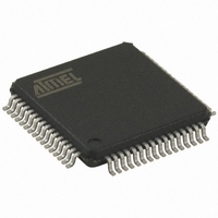
AT89C51ED2-RDTUM Atmel, AT89C51ED2-RDTUM Datasheet - Page 41

AT89C51ED2-RDTUM
Manufacturer Part Number
AT89C51ED2-RDTUM
Description
IC 8051 MCU FLASH 64K 64VQFP
Manufacturer
Atmel
Series
89Cr
Datasheet
1.ATWEBDVK-02RC.pdf
(137 pages)
Specifications of AT89C51ED2-RDTUM
Core Processor
8051
Core Size
8-Bit
Speed
60MHz
Connectivity
SPI, UART/USART
Peripherals
POR, PWM, WDT
Number Of I /o
50
Program Memory Size
64KB (64K x 8)
Program Memory Type
FLASH
Eeprom Size
2K x 8
Ram Size
2K x 8
Voltage - Supply (vcc/vdd)
2.7 V ~ 5.5 V
Oscillator Type
External
Operating Temperature
-40°C ~ 85°C
Package / Case
64-TQFP, 64-VQFP
Processor Series
AT89x
Core
8051
Data Bus Width
8 bit
Data Ram Size
2 KB
Interface Type
UART, SPI
Maximum Clock Frequency
60 MHz
Number Of Programmable I/os
50
Number Of Timers
3
Operating Supply Voltage
2.7 V to 5.5 V
Maximum Operating Temperature
+ 85 C
Mounting Style
SMD/SMT
3rd Party Development Tools
PK51, CA51, A51, ULINK2
Minimum Operating Temperature
- 40 C
Cpu Family
AT89
Device Core
8051
Device Core Size
8b
Frequency (max)
40MHz
Total Internal Ram Size
2KB
# I/os (max)
50
Number Of Timers - General Purpose
3
Operating Supply Voltage (typ)
3.3/5V
Operating Supply Voltage (max)
5.5V
Operating Supply Voltage (min)
2.7V
Instruction Set Architecture
CISC
Operating Temp Range
-40C to 85C
Operating Temperature Classification
Industrial
Mounting
Surface Mount
Pin Count
64
Package Type
VQFP
For Use With
AT89OCD-01 - USB EMULATOR FOR AT8XC51 MCU
Lead Free Status / RoHS Status
Lead free / RoHS Compliant
Data Converters
-
Lead Free Status / Rohs Status
Details
Available stocks
Company
Part Number
Manufacturer
Quantity
Price
Company:
Part Number:
AT89C51ED2-RDTUM
Manufacturer:
ATMEL
Quantity:
19 090
Part Number:
AT89C51ED2-RDTUM
Manufacturer:
MICROCHIP/微芯
Quantity:
20 000
4235K–8051–05/08
Table 13-4.
There are two additional registers associated with each of the PCA modules. They are CCAPnH
and CCAPnL and these are the registers that store the 16-bit count when a capture occurs or a
compare should occur. When a module is used in the PWM mode these registers are used to
control the duty cycle of the output (See Table 13-5 & Table 13-6).
Table 13-5.
CCAP0H - PCA Module 0 Compare/Capture Control Register High (0FAh)
CCAP1H - PCA Module 1 Compare/Capture Control Register High (0FBh)
CCAP2H - PCA Module 2 Compare/Capture Control Register High (0FCh)
CCAP3H - PCA Module 3 Compare/Capture Control Register High (0FDh)
CCAP4H - PCA Module 4 Compare/Capture Control Register High (0FEh)
Reset Value = 0000 0000b
Not bit addressable
ECOMn
Number
0
X
X
X
1
1
1
1
7 - 0
Bit
7
-
CAPPn
0
1
0
1
0
0
0
0
Mnemonic
PCA Module Modes (CCAPMn Registers)
CCAPnH Registers (n = 0 - 4)
Bit
6
-
-
CAPNn
0
0
1
1
0
0
0
0
Description
PCA Module n Compare/Capture Control
CCAPnH Value
MATn
5
-
0
0
0
0
1
1
0
1
TOGn
X
0
0
0
0
0
1
0
4
-
PWMm
0
0
0
0
0
0
1
0
3
-
ECCFn
X
X
X
X
X
X
0
0
AT89C51RD2/ED2
Module Function
16-bit capture by a positive-edge
trigger on CEXn
16-bit capture by a negative trigger on
CEXn
16-bit capture by a transition on CEXn
16-bit Software Timer/Compare mode.
16-bit High Speed Output
8-bit PWM
Watchdog Timer (module 4 only)
No Operation
2
-
1
-
0
-
41


