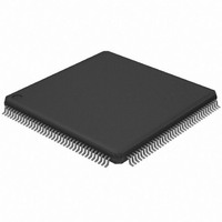
AT32UC3A0256-ALUT Atmel, AT32UC3A0256-ALUT Datasheet - Page 107

AT32UC3A0256-ALUT
Manufacturer Part Number
AT32UC3A0256-ALUT
Description
IC MCU AVR32 256KB FLASH 144LQFP
Manufacturer
Atmel
Series
AVR®32 UC3r
Specifications of AT32UC3A0256-ALUT
Core Processor
AVR
Core Size
32-Bit
Speed
66MHz
Connectivity
EBI/EMI, Ethernet, I²C, SPI, SSC, UART/USART, USB OTG
Peripherals
Brown-out Detect/Reset, POR, PWM, WDT
Number Of I /o
109
Program Memory Size
256KB (256K x 8)
Program Memory Type
FLASH
Ram Size
64K x 8
Voltage - Supply (vcc/vdd)
1.65 V ~ 1.95 V
Data Converters
A/D 8x10b
Oscillator Type
Internal
Operating Temperature
-40°C ~ 85°C
Package / Case
144-LQFP
Processor Series
AT32UC3x
Core
AVR32
Data Bus Width
32 bit
Data Ram Size
64 KB
Interface Type
2-Wire, RS-485, SPI, USART
Maximum Clock Frequency
66 MHz
Number Of Programmable I/os
69
Number Of Timers
3
Maximum Operating Temperature
+ 85 C
Mounting Style
SMD/SMT
3rd Party Development Tools
EWAVR32, EWAVR32-BL, KSK-EVK1100-PL
Development Tools By Supplier
ATAVRDRAGON, ATSTK500, ATSTK600, ATAVRISP2, ATAVRONEKIT, ATEXTWIFI, ATEVK1100, ATEVK1105
Minimum Operating Temperature
- 40 C
Controller Family/series
AT32UC3A
No. Of I/o's
109
Ram Memory Size
64KB
Cpu Speed
66MHz
No. Of Timers
1
Rohs Compliant
Yes
Package
144LQFP
Device Core
AVR32
Family Name
AT32
Maximum Speed
66 MHz
Operating Supply Voltage
1.8|3.3 V
For Use With
ATEVK1105 - KIT EVAL FOR AT32UC3A0ATAVRONEKIT - KIT AVR/AVR32 DEBUGGER/PROGRMMR770-1008 - ISP 4PORT ATMEL AVR32 MCU SPIATEVK1100 - KIT DEV/EVAL FOR AVR32 AT32UC3A
Lead Free Status / RoHS Status
Lead free / RoHS Compliant
Eeprom Size
-
Lead Free Status / Rohs Status
Lead free / RoHS Compliant
Available stocks
Company
Part Number
Manufacturer
Quantity
Price
Company:
Part Number:
AT32UC3A0256-ALUT
Manufacturer:
ATMEL
Quantity:
167
- Current page: 107 of 826
- Download datasheet (20Mb)
17.5
17.5.1
17.5.1.1
17.5.1.2
17.5.2
32058J–AVR32–04/11
Functional Description
External Interrupts
Non-Maskable Interrupt
Synchronization of external interrupts
Wakeup
To enable an external interrupt EXTINTn must be written to 1 in register EN. Similarly, writing
EXTINTn to 1 in register DIS disables the interrupt. The status of each Interrupt line can be
observed in the CTRL register.
Each external interrupt pin EXTINTn can be configured to produce an interrupt on rising or fall-
ing edge, or high or low level. External interrupts are configured by the MODE, EDGE, and
LEVEL registers. Each interrupt n has a bit INTn in each of these registers.
Similarly, each interrupt has a corresponding bit in each of the interrupt control and status regis-
ters. Writing 1 to the INTn strobe in IER enables the external interrupt on pin EXTINTn, while
writing 1 to INTn in IDR disables the external interrupt. IMR can be read to check which inter-
rupts are enabled. When the interrupt triggers, the corresponding bit in ISR will be set. The flag
remains set until the corresponding strobe bit in ICR is written to 1.
Writing INTn in MODE to 0 enables edge triggered interrupts, while writing the bit to 1 enables
level triggered interrupts.
If EXTINTn is configured as an edge triggered interrupt, writing INTn in EDGE to 0 will trigger the
interrupt on falling edge, while writing the bit to 1 will trigger the interrupt on rising edge.
If EXTINTn is configured as a level triggered interrupt, writing INTn in LEVEL to 0 will trigger the
interrupt on low level, while writing the bit to 1 will trigger the interrupt on high level.
To remove spikes that are longer than the clock period in the current mode each external inter-
rupt contains a filter that can be enabled by writing 1 to INTn to FILTER.
Each interrupt line can be made asynchronous by writing 1 to INTn in the ASYNC register. This
will route the interrupt signal through the asynchronous path of the module. All edge interrupts
will be interpreted as level interrupts and the filter is disabled.
The pin value of the EXTINTn pins is normally synchronized to the CPU clock, so spikes shorter
than a CPU clock cycle are not guaranteed to produce an interrupt. In Stop mode, spikes shorter
than a 32 KHz clock cycle are not guaranteed to produce an interrupt.
In Static mode, only unsynchronized interrupts remain active, and any short spike on this inter-
rupt will wake up the device.
The External interrupts can be used to wake up the part from sleep modes. The wakeup can be
interpreted in two ways. If the corresponding bit in IMR is set, then the execution starts at the
interrupt handler for this interrupt. If the bit in IMR is not set, then the execution starts from the
next instruction after the sleep instruction.
The NMI supports the same features as the external interrupts, and is accessed through the
same registers. The description in
instead of the INTn bits.
Section 17.5.1
should be followed, accessing the NMI bit
AT32UC3A
107
Related parts for AT32UC3A0256-ALUT
Image
Part Number
Description
Manufacturer
Datasheet
Request
R

Part Number:
Description:
DEV KIT FOR AVR/AVR32
Manufacturer:
Atmel
Datasheet:

Part Number:
Description:
INTERVAL AND WIPE/WASH WIPER CONTROL IC WITH DELAY
Manufacturer:
ATMEL Corporation
Datasheet:

Part Number:
Description:
Low-Voltage Voice-Switched IC for Hands-Free Operation
Manufacturer:
ATMEL Corporation
Datasheet:

Part Number:
Description:
MONOLITHIC INTEGRATED FEATUREPHONE CIRCUIT
Manufacturer:
ATMEL Corporation
Datasheet:

Part Number:
Description:
AM-FM Receiver IC U4255BM-M
Manufacturer:
ATMEL Corporation
Datasheet:

Part Number:
Description:
Monolithic Integrated Feature Phone Circuit
Manufacturer:
ATMEL Corporation
Datasheet:

Part Number:
Description:
Multistandard Video-IF and Quasi Parallel Sound Processing
Manufacturer:
ATMEL Corporation
Datasheet:

Part Number:
Description:
High-performance EE PLD
Manufacturer:
ATMEL Corporation
Datasheet:

Part Number:
Description:
8-bit Flash Microcontroller
Manufacturer:
ATMEL Corporation
Datasheet:

Part Number:
Description:
2-Wire Serial EEPROM
Manufacturer:
ATMEL Corporation
Datasheet:


