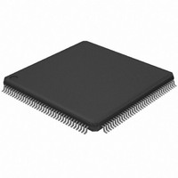
AT32UC3A0256-ALUT Atmel, AT32UC3A0256-ALUT Datasheet - Page 315

AT32UC3A0256-ALUT
Manufacturer Part Number
AT32UC3A0256-ALUT
Description
IC MCU AVR32 256KB FLASH 144LQFP
Manufacturer
Atmel
Series
AVR®32 UC3r
Specifications of AT32UC3A0256-ALUT
Core Processor
AVR
Core Size
32-Bit
Speed
66MHz
Connectivity
EBI/EMI, Ethernet, I²C, SPI, SSC, UART/USART, USB OTG
Peripherals
Brown-out Detect/Reset, POR, PWM, WDT
Number Of I /o
109
Program Memory Size
256KB (256K x 8)
Program Memory Type
FLASH
Ram Size
64K x 8
Voltage - Supply (vcc/vdd)
1.65 V ~ 1.95 V
Data Converters
A/D 8x10b
Oscillator Type
Internal
Operating Temperature
-40°C ~ 85°C
Package / Case
144-LQFP
Processor Series
AT32UC3x
Core
AVR32
Data Bus Width
32 bit
Data Ram Size
64 KB
Interface Type
2-Wire, RS-485, SPI, USART
Maximum Clock Frequency
66 MHz
Number Of Programmable I/os
69
Number Of Timers
3
Maximum Operating Temperature
+ 85 C
Mounting Style
SMD/SMT
3rd Party Development Tools
EWAVR32, EWAVR32-BL, KSK-EVK1100-PL
Development Tools By Supplier
ATAVRDRAGON, ATSTK500, ATSTK600, ATAVRISP2, ATAVRONEKIT, ATEXTWIFI, ATEVK1100, ATEVK1105
Minimum Operating Temperature
- 40 C
Controller Family/series
AT32UC3A
No. Of I/o's
109
Ram Memory Size
64KB
Cpu Speed
66MHz
No. Of Timers
1
Rohs Compliant
Yes
Package
144LQFP
Device Core
AVR32
Family Name
AT32
Maximum Speed
66 MHz
Operating Supply Voltage
1.8|3.3 V
For Use With
ATEVK1105 - KIT EVAL FOR AT32UC3A0ATAVRONEKIT - KIT AVR/AVR32 DEBUGGER/PROGRMMR770-1008 - ISP 4PORT ATMEL AVR32 MCU SPIATEVK1100 - KIT DEV/EVAL FOR AVR32 AT32UC3A
Lead Free Status / RoHS Status
Lead free / RoHS Compliant
Eeprom Size
-
Lead Free Status / Rohs Status
Lead free / RoHS Compliant
Available stocks
Company
Part Number
Manufacturer
Quantity
Price
Company:
Part Number:
AT32UC3A0256-ALUT
Manufacturer:
ATMEL
Quantity:
167
- Current page: 315 of 826
- Download datasheet (20Mb)
26.7.3.5
Figure 26-14. Asynchronous Start Bit Detection
32058J–AVR32–04/11
Manchester Decoder
Manchester
Sampling
encoded
(16 x)
Clock
data
When the MAN field in MR register is set to 1, the Manchester decoder is enabled. The decoder
performs both preamble and start frame delimiter detection. One input line is dedicated to Man-
chester encoded input data.
An optional preamble sequence can be defined, its length is user-defined and totally indepen-
dent of the emitter side. Use RX_PL in MAN register to configure the length of the preamble
sequence. If the length is set to 0, no preamble is detected and the function is disabled. In addi-
tion, the polarity of the input stream is programmable with RX_MPOL field in MAN register.
Depending on the desired application the preamble pattern matching is to be defined via the
RX_PP field in MAN. See
Unlike preamble, the start frame delimiter is shared between Manchester Encoder and Decoder.
So, if ONEBIT field is set to 1, only a zero encoded Manchester can be detected as a valid start
frame delimiter. If ONEBIT is set to 0, only a sync pattern is detected as a valid start frame
delimiter. Decoder operates by detecting transition on incoming stream. If RXD is sampled dur-
ing one quarter of a bit time at zero, a start bit is detected. See
sample pulse rejection mechanism applies.
The receiver is activated and starts Preamble and Frame Delimiter detection, sampling the data
at one quarter and then three quarters. If a valid preamble pattern or start frame delimiter is
detected, the receiver continues decoding with the same synchronization. If the stream does not
match a valid pattern or a valid start frame delimiter, the receiver re-synchronizes on the next
valid edge.The minimum time threshold to estimate the bit value is three quarters of a bit time.
If a valid preamble (if used) followed with a valid start frame delimiter is detected, the incoming
stream is decoded into NRZ data and passed to USART for processing.
316
USART, the receiver is also able to detect Manchester code violation. A code violation is a lack
of transition in the middle of a bit cell. In this case, MANE flag in CSR register is raised. It is
cleared by writing the Control Register (CR) with the RSTSTA bit at 1. See
316
for an example of Manchester error detection during data phase.
illustrates Manchester pattern mismatch. When incoming data stream is passed to the
Txd
1
2
3
4
Detection
Figure 26-9 on page 312
Start
for available preamble patterns.
Figure 26-14 on page
Figure 26-15 on page
Figure 26-16 on page
AT32UC3A
315.. The
315
Related parts for AT32UC3A0256-ALUT
Image
Part Number
Description
Manufacturer
Datasheet
Request
R

Part Number:
Description:
DEV KIT FOR AVR/AVR32
Manufacturer:
Atmel
Datasheet:

Part Number:
Description:
INTERVAL AND WIPE/WASH WIPER CONTROL IC WITH DELAY
Manufacturer:
ATMEL Corporation
Datasheet:

Part Number:
Description:
Low-Voltage Voice-Switched IC for Hands-Free Operation
Manufacturer:
ATMEL Corporation
Datasheet:

Part Number:
Description:
MONOLITHIC INTEGRATED FEATUREPHONE CIRCUIT
Manufacturer:
ATMEL Corporation
Datasheet:

Part Number:
Description:
AM-FM Receiver IC U4255BM-M
Manufacturer:
ATMEL Corporation
Datasheet:

Part Number:
Description:
Monolithic Integrated Feature Phone Circuit
Manufacturer:
ATMEL Corporation
Datasheet:

Part Number:
Description:
Multistandard Video-IF and Quasi Parallel Sound Processing
Manufacturer:
ATMEL Corporation
Datasheet:

Part Number:
Description:
High-performance EE PLD
Manufacturer:
ATMEL Corporation
Datasheet:

Part Number:
Description:
8-bit Flash Microcontroller
Manufacturer:
ATMEL Corporation
Datasheet:

Part Number:
Description:
2-Wire Serial EEPROM
Manufacturer:
ATMEL Corporation
Datasheet:


