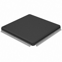
AT32UC3A0256-ALUT Atmel, AT32UC3A0256-ALUT Datasheet - Page 513

AT32UC3A0256-ALUT
Manufacturer Part Number
AT32UC3A0256-ALUT
Description
IC MCU AVR32 256KB FLASH 144LQFP
Manufacturer
Atmel
Series
AVR®32 UC3r
Specifications of AT32UC3A0256-ALUT
Core Processor
AVR
Core Size
32-Bit
Speed
66MHz
Connectivity
EBI/EMI, Ethernet, I²C, SPI, SSC, UART/USART, USB OTG
Peripherals
Brown-out Detect/Reset, POR, PWM, WDT
Number Of I /o
109
Program Memory Size
256KB (256K x 8)
Program Memory Type
FLASH
Ram Size
64K x 8
Voltage - Supply (vcc/vdd)
1.65 V ~ 1.95 V
Data Converters
A/D 8x10b
Oscillator Type
Internal
Operating Temperature
-40°C ~ 85°C
Package / Case
144-LQFP
Processor Series
AT32UC3x
Core
AVR32
Data Bus Width
32 bit
Data Ram Size
64 KB
Interface Type
2-Wire, RS-485, SPI, USART
Maximum Clock Frequency
66 MHz
Number Of Programmable I/os
69
Number Of Timers
3
Maximum Operating Temperature
+ 85 C
Mounting Style
SMD/SMT
3rd Party Development Tools
EWAVR32, EWAVR32-BL, KSK-EVK1100-PL
Development Tools By Supplier
ATAVRDRAGON, ATSTK500, ATSTK600, ATAVRISP2, ATAVRONEKIT, ATEXTWIFI, ATEVK1100, ATEVK1105
Minimum Operating Temperature
- 40 C
Controller Family/series
AT32UC3A
No. Of I/o's
109
Ram Memory Size
64KB
Cpu Speed
66MHz
No. Of Timers
1
Rohs Compliant
Yes
Package
144LQFP
Device Core
AVR32
Family Name
AT32
Maximum Speed
66 MHz
Operating Supply Voltage
1.8|3.3 V
For Use With
ATEVK1105 - KIT EVAL FOR AT32UC3A0ATAVRONEKIT - KIT AVR/AVR32 DEBUGGER/PROGRMMR770-1008 - ISP 4PORT ATMEL AVR32 MCU SPIATEVK1100 - KIT DEV/EVAL FOR AVR32 AT32UC3A
Lead Free Status / RoHS Status
Lead free / RoHS Compliant
Eeprom Size
-
Lead Free Status / Rohs Status
Lead free / RoHS Compliant
Available stocks
Company
Part Number
Manufacturer
Quantity
Price
Company:
Part Number:
AT32UC3A0256-ALUT
Manufacturer:
ATMEL
Quantity:
167
- Current page: 513 of 826
- Download datasheet (20Mb)
30.7.2.6
30.7.2.7
30.7.2.8
30.7.2.9
32058J–AVR32–04/11
Suspend and Wake-Up
Address Setup
Detach
Remote Wake-Up
See
The USB device address is set up according to the USB protocol:
Once the USB device address is configured, the controller filters the packets to only accept
those targeting the address stored in UADD.
UADD and ADDEN shall not be written all at once.
UADD and ADDEN are cleared by hardware:
When UADD or ADDEN is cleared, the default device address 0 is used.
When an idle USB bus state has been detected for 3 ms, the controller raises the Suspend inter-
rupt (SUSP). The firmware may then set the FRZCLK bit to reduce power consumption. The
MCU can also enter the Idle or Frozen sleep mode to lower again power consumption.
To recover from the Suspend mode, the firmware should wait for the Wake-Up interrupt
(WAKEUP), which is raised when a non-idle event is detected, then clear FRZCLK.
As the WAKEUP interrupt is raised when a non-idle event is detected, it can occur whether the
controller is in the Suspend mode or not. The SUSP and WAKEUP interrupts are thus indepen-
dent of each other except that one’s flag is cleared by hardware when the other is raised.
The reset value of the DETACH bit is 1.
It is possible to initiate a device re-enumeration simply by setting then clearing DETACH.
DETACH acts on the pull-up connections of the D+ and D- pads. See
page 506
The Remote Wake-Up request (also known as Upstream Resume) is the only one the device
may send on its own initiative, but the device should have beforehand been allowed to by a
DEVICE_REMOTE_WAKEUP request from the host.
• First, the USB controller must have detected a “Suspend” state on the bus, i.e. the Remote
•after all kinds of resets, the USB device address is 0;
•the host starts a SETUP transaction with a SET_ADDRESS(addr) request;
•the firmware records this address into the UADD bit-field, leaving the ADDEN bit cleared, so
•the firmware sends a zero-length IN packet from the control endpoint;
•the firmware enables the recorded USB device address by setting ADDEN.
•on a hardware reset;
•when the USB macro is disabled (USBE = 0);
•when a USB reset is detected.
Wake-Up request can only be sent after a SUSP interrupt has been raised.
the actual address is still 0;
Section 30.7.1.6 on page 506
for further details.
for more details about DPRAM management.
Section 30.7.1.5.1 on
AT32UC3A
513
Related parts for AT32UC3A0256-ALUT
Image
Part Number
Description
Manufacturer
Datasheet
Request
R

Part Number:
Description:
DEV KIT FOR AVR/AVR32
Manufacturer:
Atmel
Datasheet:

Part Number:
Description:
INTERVAL AND WIPE/WASH WIPER CONTROL IC WITH DELAY
Manufacturer:
ATMEL Corporation
Datasheet:

Part Number:
Description:
Low-Voltage Voice-Switched IC for Hands-Free Operation
Manufacturer:
ATMEL Corporation
Datasheet:

Part Number:
Description:
MONOLITHIC INTEGRATED FEATUREPHONE CIRCUIT
Manufacturer:
ATMEL Corporation
Datasheet:

Part Number:
Description:
AM-FM Receiver IC U4255BM-M
Manufacturer:
ATMEL Corporation
Datasheet:

Part Number:
Description:
Monolithic Integrated Feature Phone Circuit
Manufacturer:
ATMEL Corporation
Datasheet:

Part Number:
Description:
Multistandard Video-IF and Quasi Parallel Sound Processing
Manufacturer:
ATMEL Corporation
Datasheet:

Part Number:
Description:
High-performance EE PLD
Manufacturer:
ATMEL Corporation
Datasheet:

Part Number:
Description:
8-bit Flash Microcontroller
Manufacturer:
ATMEL Corporation
Datasheet:

Part Number:
Description:
2-Wire Serial EEPROM
Manufacturer:
ATMEL Corporation
Datasheet:


