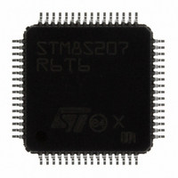
STM8S207R6T6 STMicroelectronics, STM8S207R6T6 Datasheet - Page 67

STM8S207R6T6
Manufacturer Part Number
STM8S207R6T6
Description
MCU 8BIT 32K MEMORY 64-LQFP
Manufacturer
STMicroelectronics
Series
STM8Sr
Datasheet
1.STEVAL-MKI030V1.pdf
(105 pages)
Specifications of STM8S207R6T6
Mfg Application Notes
STM8S Getting Started
Core Processor
STM8
Core Size
8-Bit
Speed
24MHz
Connectivity
I²C, IrDA, LIN, SPI, UART/USART
Peripherals
Brown-out Detect/Reset, POR, PWM, WDT
Number Of I /o
52
Program Memory Size
32KB (32K x 8)
Program Memory Type
FLASH
Eeprom Size
1K x 8
Ram Size
2K x 8
Voltage - Supply (vcc/vdd)
2.95 V ~ 5.5 V
Data Converters
A/D 16x10b
Oscillator Type
Internal
Operating Temperature
-40°C ~ 85°C
Package / Case
64-LQFP
Processor Series
STM8S20x
Core
STM8
Data Bus Width
8 bit
Data Ram Size
6 KB
Interface Type
CAN, 12C, SPI, UART
Maximum Clock Frequency
24 MHz
Number Of Programmable I/os
52
Number Of Timers
2
Operating Supply Voltage
2.95 V to 5.5 V
Maximum Operating Temperature
+ 85 C
Mounting Style
SMD/SMT
3rd Party Development Tools
EWSTM8
Development Tools By Supplier
STICE-SYS001
Minimum Operating Temperature
- 40 C
On-chip Adc
10 bit
For Use With
497-10032 - EVAL KIT MOTOR CONTROL STM8S497-10031 - EVAL KIT TOUCH SENSING STM8S497-8852 - BOARD DEMO STM8S207R6/LIS331DLH497-8851 - BOARD DEMO STM8S207R6/LIS331DLH497-10592 - BOARD DAUGHTER FOR STM8S207/8497-10593 - KIT STARTER FOR STM8S207/8 SER497-8506 - BOARD EVAL FOR STM8S
Lead Free Status / RoHS Status
Lead free / RoHS Compliant
Other names
497-8953
STM8S207R6T6
STM8S207R6T6
Available stocks
Company
Part Number
Manufacturer
Quantity
Price
Company:
Part Number:
STM8S207R6T6
Manufacturer:
STMicroelectronics
Quantity:
80
Company:
Part Number:
STM8S207R6T6
Manufacturer:
STMicroelectronics
Quantity:
10 000
Part Number:
STM8S207R6T6
Manufacturer:
ST
Quantity:
20 000
STM8S207xx, STM8S208xx
Table 32.
1. C is approximately equivalent to 2 x crystal Cload.
2. The oscillator selection can be optimized in terms of supply current using a high quality resonator with small R
3. Data based on characterization results, not tested in production.
4.
Figure 17. HSE oscillator circuit diagram
HSE oscillator critical g
R
L
C
Co: Shunt capacitance (see crystal specification)
C
g
g
t
m
m
SU(HSE)
mcrit
m
m
L1
Symbol
I
DD(HSE)
: Notional inductance (see crystal specification)
Refer to crystal manufacturer for more details
reached. This value is measured for a standard crystal resonator and it can vary significantly with the crystal manufacturer.
: Notional resistance (see crystal specification)
: Notional capacitance (see crystal specification)
f
>> g
C
t
=C
HSE
R
g
SU(HSE)
(1)
m
F
R
L
C
=
L2
m
m
m
mcrit
(4)
Resonator
=C: Grounded external capacitance
2
is the start-up time measured from the moment it is enabled (by software) to a stabilized 24 MHz oscillation is
C
External high speed oscillator
frequency
Feedback resistor
Recommended load capacitance
HSE oscillator power consumption
Oscillator transconductance
Startup time
O
HSE oscillator characteristics
f
HSE
2
Parameter
R
m
m
formula
2Co
C
C
L1
L2
+
C
2
Resonator
(2)
Doc ID 14733 Rev 11
V
OSCIN
OSCOUT
f
f
OSC
OSC
DD
Conditions
C = 20 pF,
C = 10 pF,
is stabilized
= 24 MHz
= 24 MHz
Min
1
5
R
g
F
m
Typ
220
1
Consumption
Electrical characteristics
control
f
1.5 (stabilized)
HSE
2 (stabilized)
6 (startup)
6 (startup)
to core
Max
24
20
m
value.
(3)
STM8
(3)
67/105
mA/V
MHz
Unit
mA
ms
k
pF


