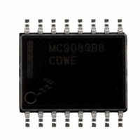
MC908QB8CDWE Freescale Semiconductor, MC908QB8CDWE Datasheet - Page 50

MC908QB8CDWE
Manufacturer Part Number
MC908QB8CDWE
Description
IC MCU 8BIT 8K FLASH 16-SOIC
Manufacturer
Freescale Semiconductor
Series
HC08r
Datasheet
1.MC908QB8CDWE.pdf
(236 pages)
Specifications of MC908QB8CDWE
Core Processor
HC08
Core Size
8-Bit
Speed
8MHz
Connectivity
SCI, SPI
Peripherals
LVD, POR, PWM
Number Of I /o
13
Program Memory Size
8KB (8K x 8)
Program Memory Type
FLASH
Ram Size
256 x 8
Voltage - Supply (vcc/vdd)
2.7 V ~ 5.5 V
Data Converters
A/D 10x10b
Oscillator Type
Internal
Operating Temperature
-40°C ~ 85°C
Package / Case
16-SOIC (0.300", 7.5mm Width)
Processor Series
HC08QB
Core
HC08
Data Bus Width
8 bit
Data Ram Size
256 B
Interface Type
SCI, SPI
Maximum Clock Frequency
8 MHz
Number Of Programmable I/os
14
Number Of Timers
4
Operating Supply Voltage
3 V to 5 V
Maximum Operating Temperature
+ 85 C
Mounting Style
SMD/SMT
Development Tools By Supplier
FSICEBASE, M68CBL05AE, DEMO908QB8, DEMO908QC16
Minimum Operating Temperature
- 40 C
On-chip Adc
10 bit
For Use With
DEMO908QB8 - BOARD DEMO FOR MC68HC908QB8
Lead Free Status / RoHS Status
Lead free / RoHS Compliant
Eeprom Size
-
Lead Free Status / Rohs Status
Details
Available stocks
Company
Part Number
Manufacturer
Quantity
Price
Part Number:
MC908QB8CDWE
Manufacturer:
FREESCALE
Quantity:
20 000
Part Number:
MC908QB8CDWER
Manufacturer:
FREESCALE
Quantity:
20 000
- Current page: 50 of 236
- Download datasheet (3Mb)
Analog-to-Digital Converter (ADC10) Module
ADLSMP — Long Sample Time Configuration
ACLKEN — Asynchronous Clock Source Enable
50
This bit configures the sample time of the ADC10 to either 3.5 or 23.5 ADCK clock cycles. This adjusts
the sample period to allow higher impedance inputs to be accurately sampled or to maximize
conversion speed for lower impedance inputs. Longer sample times can also be used to lower overall
power consumption in continuous conversion mode if high conversion rates are not required.
This bit enables the asynchronous clock source as the input clock to generate the internal clock ADCK,
and allows operation in stop mode. The asynchronous clock source will operate between 1 MHz and
2 MHz if ADLPC is clear, and between 0.5 MHz and 1 MHz if ADLPC is set.
1 = Long sample time (23.5 cycles)
0 = Short sample time (3.5 cycles)
1 = The asynchronous clock is selected as the input clock source (the clock generator is only
0 = ADICLK specifies the input clock source and conversions will not continue in stop mode
enabled during the conversion)
MC68HC908QB8 Data Sheet, Rev. 3
Freescale Semiconductor
Related parts for MC908QB8CDWE
Image
Part Number
Description
Manufacturer
Datasheet
Request
R
Part Number:
Description:
Manufacturer:
Freescale Semiconductor, Inc
Datasheet:
Part Number:
Description:
Manufacturer:
Freescale Semiconductor, Inc
Datasheet:
Part Number:
Description:
Manufacturer:
Freescale Semiconductor, Inc
Datasheet:
Part Number:
Description:
Manufacturer:
Freescale Semiconductor, Inc
Datasheet:
Part Number:
Description:
Manufacturer:
Freescale Semiconductor, Inc
Datasheet:
Part Number:
Description:
Manufacturer:
Freescale Semiconductor, Inc
Datasheet:
Part Number:
Description:
Manufacturer:
Freescale Semiconductor, Inc
Datasheet:
Part Number:
Description:
Manufacturer:
Freescale Semiconductor, Inc
Datasheet:
Part Number:
Description:
Manufacturer:
Freescale Semiconductor, Inc
Datasheet:
Part Number:
Description:
Manufacturer:
Freescale Semiconductor, Inc
Datasheet:
Part Number:
Description:
Manufacturer:
Freescale Semiconductor, Inc
Datasheet:
Part Number:
Description:
Manufacturer:
Freescale Semiconductor, Inc
Datasheet:
Part Number:
Description:
Manufacturer:
Freescale Semiconductor, Inc
Datasheet:
Part Number:
Description:
Manufacturer:
Freescale Semiconductor, Inc
Datasheet:
Part Number:
Description:
Manufacturer:
Freescale Semiconductor, Inc
Datasheet:


