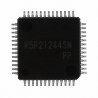
R5F21244SNFP#U0 Renesas Electronics America, R5F21244SNFP#U0 Datasheet - Page 57

R5F21244SNFP#U0
Manufacturer Part Number
R5F21244SNFP#U0
Description
IC R8C MCU FLASH 16K 52LQFP
Manufacturer
Renesas Electronics America
Series
M16C™ M16C/R8C/Tiny/24r
Datasheets
1.R5F211A2SPU0.pdf
(300 pages)
2.R5F21246SDFPU0.pdf
(61 pages)
3.R5F21246SDFPU0.pdf
(527 pages)
Specifications of R5F21244SNFP#U0
Core Processor
R8C
Core Size
16-Bit
Speed
20MHz
Connectivity
I²C, LIN, SIO, SSU, UART/USART
Peripherals
POR, Voltage Detect, WDT
Number Of I /o
41
Program Memory Size
16KB (16K x 8)
Program Memory Type
FLASH
Ram Size
1K x 8
Voltage - Supply (vcc/vdd)
2.2 V ~ 5.5 V
Data Converters
A/D 12x10b
Oscillator Type
Internal
Operating Temperature
-20°C ~ 85°C
Package / Case
52-LQFP
For Use With
R0K521256S000BE - KIT EVAL STARTER FOR R8C/25
Lead Free Status / RoHS Status
Lead free / RoHS Compliant
Eeprom Size
-
Available stocks
Company
Part Number
Manufacturer
Quantity
Price
Part Number:
R5F21244SNFP#U0R5F21244SNFP#V2
Manufacturer:
Renesas Electronics America
Quantity:
10 000
- Current page: 57 of 300
- Download datasheet (2Mb)
Rev.2.00 Oct 17, 2005
REJ09B0001-0200
Chapter 3 Functions
R0L/R0
A0/A0
dsp:8[A0]
dsp:16[A0] dsp:16[A1]
dsp:20[A0] dsp:20[A1]
R2R0
(4) Operation
(5) Function
(6) Selectable src / dest (label)
(7) Flag change
(8) Description example
(9) Related instructions
Explains the operation of the instruction using symbols.
Explains the function of the instruction and precautions to be taken when using the instruction.
If the instruction has operands, the valid formats are listed here.
(a) Items that can be selected as src (source)
(b) Items that can be selected as dest (destination)
(c) Addressing modes that can be selected
(d) Addressing modes that cannot be selected
(e) Shown on the left side of the slash (R0H) is the addressing mode when data is handled in bytes (8 bits).
Shows a flag change that occurs after the instruction is executed. The symbols in the table mean the
following.
Description examples for the instruction.
Related instructions that cause an operation similar or opposite to that of the instruction.
Shown on the right side of the slash (R1) is the addressing mode when data is handled in words (16 bits).
“
“O” The flag changes depending on a condition.
—
” The flag does not change.
R0H/R1
A1/A1
dsp:8[A1]
R3R1
page 37 of 263
src
R1L/R2
[A0]
dsp:8[SB]
dsp:16[SB]
abs20
A1A0
R1H/R3
[A1]
dsp:8[FB] dsp:8[A0]
abs16
#IMM
dsp:8[SP]
R0L/R0
A0/A0
dsp:16[A0] dsp:16[A1] dsp:16[SB] abs16
dsp:20[A0] dsp:20[A1] abs20
R2R0
R0H/R1
A1/A1
dsp:8[A1]
R3R1
dest
R1L/R2
[A0]
dsp:8[SB]
A1A0
3.1 Guide to This Chapter
R1H/R3
[A1]
dsp:8[FB]
dsp:8[SP]
(a)
(b)
(c)
(d)
(e)
Related parts for R5F21244SNFP#U0
Image
Part Number
Description
Manufacturer
Datasheet
Request
R

Part Number:
Description:
KIT STARTER FOR M16C/29
Manufacturer:
Renesas Electronics America
Datasheet:

Part Number:
Description:
KIT STARTER FOR R8C/2D
Manufacturer:
Renesas Electronics America
Datasheet:

Part Number:
Description:
R0K33062P STARTER KIT
Manufacturer:
Renesas Electronics America
Datasheet:

Part Number:
Description:
KIT STARTER FOR R8C/23 E8A
Manufacturer:
Renesas Electronics America
Datasheet:

Part Number:
Description:
KIT STARTER FOR R8C/25
Manufacturer:
Renesas Electronics America
Datasheet:

Part Number:
Description:
KIT STARTER H8S2456 SHARPE DSPLY
Manufacturer:
Renesas Electronics America
Datasheet:

Part Number:
Description:
KIT STARTER FOR R8C38C
Manufacturer:
Renesas Electronics America
Datasheet:

Part Number:
Description:
KIT STARTER FOR R8C35C
Manufacturer:
Renesas Electronics America
Datasheet:

Part Number:
Description:
KIT STARTER FOR R8CL3AC+LCD APPS
Manufacturer:
Renesas Electronics America
Datasheet:

Part Number:
Description:
KIT STARTER FOR RX610
Manufacturer:
Renesas Electronics America
Datasheet:

Part Number:
Description:
KIT STARTER FOR R32C/118
Manufacturer:
Renesas Electronics America
Datasheet:

Part Number:
Description:
KIT DEV RSK-R8C/26-29
Manufacturer:
Renesas Electronics America
Datasheet:

Part Number:
Description:
KIT STARTER FOR SH7124
Manufacturer:
Renesas Electronics America
Datasheet:

Part Number:
Description:
KIT STARTER FOR H8SX/1622
Manufacturer:
Renesas Electronics America
Datasheet:

Part Number:
Description:
KIT DEV FOR SH7203
Manufacturer:
Renesas Electronics America
Datasheet:


