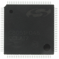
C8051F046-GQ Silicon Laboratories Inc, C8051F046-GQ Datasheet - Page 4

C8051F046-GQ
Manufacturer Part Number
C8051F046-GQ
Description
IC 8051 MCU 32K FLASH 100TQFP
Manufacturer
Silicon Laboratories Inc
Series
C8051F04xr
Specifications of C8051F046-GQ
Core Processor
8051
Core Size
8-Bit
Speed
25MHz
Connectivity
CAN, EBI/EMI, SMBus (2-Wire/I²C), SPI, UART/USART
Peripherals
Brown-out Detect/Reset, POR, PWM, Temp Sensor, WDT
Number Of I /o
64
Program Memory Size
32KB (32K x 8)
Program Memory Type
FLASH
Ram Size
4.25K x 8
Voltage - Supply (vcc/vdd)
2.7 V ~ 3.6 V
Data Converters
A/D 13x10b
Oscillator Type
Internal
Operating Temperature
-40°C ~ 85°C
Package / Case
100-TQFP, 100-VQFP
Processor Series
C8051F0x
Core
8051
Data Bus Width
8 bit
Data Ram Size
4.25 KB
Interface Type
CAN, SMBus, SPI, UART
Maximum Clock Frequency
25 MHz
Number Of Programmable I/os
64
Number Of Timers
5
Operating Supply Voltage
2.7 V to 3.6 V
Maximum Operating Temperature
+ 85 C
Mounting Style
SMD/SMT
3rd Party Development Tools
PK51, CA51, A51, ULINK2
Development Tools By Supplier
C8051F040DK
Minimum Operating Temperature
- 40 C
On-chip Adc
10 bit, 13 Channel
On-chip Dac
12 bit, 2 Channel
Package
100TQFP
Device Core
8051
Family Name
C8051F04x
Maximum Speed
25 MHz
Lead Free Status / RoHS Status
Lead free / RoHS Compliant
Eeprom Size
-
Lead Free Status / Rohs Status
Details
Other names
336-1211
Available stocks
Company
Part Number
Manufacturer
Quantity
Price
Company:
Part Number:
C8051F046-GQ
Manufacturer:
Silicon Laboratories Inc
Quantity:
10 000
Company:
Part Number:
C8051F046-GQR
Manufacturer:
AMAZING
Quantity:
67 000
Company:
Part Number:
C8051F046-GQR
Manufacturer:
Silicon Laboratories Inc
Quantity:
10 000
C8051F040/1/2/3/4/5/6/7
8. DACs, 12-Bit Voltage Mode (C8051F040/1/2/3 Only) ......................................... 105
9. Voltage Reference (C8051F040/2/4/6) ................................................................. 113
10. Voltage Reference (C8051F041/3/5/7) ................................................................. 117
11. Comparators ......................................................................................................... 121
12. CIP-51 Microcontroller ......................................................................................... 127
13. Reset Sources....................................................................................................... 165
14. Oscillators ............................................................................................................. 173
4
8.1. DAC Output Scheduling.................................................................................. 106
8.2. DAC Output Scaling/Justification .................................................................... 106
11.1.Comparator Inputs.......................................................................................... 123
12.1.Instruction Set................................................................................................. 129
12.2.Memory Organization ..................................................................................... 133
12.3.Interrupt Handler............................................................................................. 153
12.4.Power Management Modes............................................................................ 163
13.1.Power-On Reset ............................................................................................. 166
13.2.Power-Fail Reset ............................................................................................ 166
13.3.External Reset ................................................................................................ 166
13.4.Missing Clock Detector Reset ........................................................................ 167
13.5.Comparator0 Reset ........................................................................................ 167
13.6.External CNVSTR0 Pin Reset ........................................................................ 167
13.7.Watchdog Timer Reset................................................................................... 167
14.1.Programmable Internal Oscillator ................................................................... 173
7.3.2. Window Detector in Differential Mode .................................................... 102
8.1.1. Update Output On-Demand ................................................................... 106
8.1.2. Update Output Based on Timer Overflow .............................................. 106
12.1.1.Instruction and CPU Timing ................................................................... 129
12.1.2.MOVX Instruction and Program Memory ............................................... 129
12.2.1.Program Memory ................................................................................... 133
12.2.2.Data Memory.......................................................................................... 134
12.2.3.General Purpose Registers.................................................................... 134
12.2.4.Bit Addressable Locations...................................................................... 134
12.2.5.Stack ..................................................................................................... 134
12.2.6.Special Function Registers .................................................................... 135
12.2.7.Register Descriptions ............................................................................. 150
12.3.1.MCU Interrupt Sources and Vectors ...................................................... 153
12.3.2.External Interrupts.................................................................................. 154
12.3.3.Interrupt Priorities................................................................................... 156
12.3.4.Interrupt Latency .................................................................................... 156
12.3.5.Interrupt Register Descriptions............................................................... 156
12.4.1.Idle Mode ............................................................................................... 163
12.4.2.Stop Mode.............................................................................................. 164
13.7.1.Enable/Reset WDT ................................................................................ 168
13.7.2.Disable WDT .......................................................................................... 168
13.7.3.Disable WDT Lockout ............................................................................ 168
13.7.4.Setting WDT Interval .............................................................................. 168
Rev. 1.5


