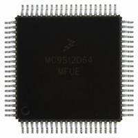
MC9S12D64MFUE Freescale Semiconductor, MC9S12D64MFUE Datasheet - Page 116

MC9S12D64MFUE
Manufacturer Part Number
MC9S12D64MFUE
Description
IC MCU 64K FLASH 25MHZ 80-QFP
Manufacturer
Freescale Semiconductor
Series
HCS12r
Datasheet
1.MC9S12A32CFUE.pdf
(128 pages)
Specifications of MC9S12D64MFUE
Core Processor
HCS12
Core Size
16-Bit
Speed
25MHz
Connectivity
CAN, I²C, SCI, SPI
Peripherals
PWM, WDT
Number Of I /o
59
Program Memory Size
64KB (64K x 8)
Program Memory Type
FLASH
Eeprom Size
1K x 8
Ram Size
4K x 8
Voltage - Supply (vcc/vdd)
2.35 V ~ 5.25 V
Data Converters
A/D 16x10b
Oscillator Type
Internal
Operating Temperature
-40°C ~ 125°C
Package / Case
80-QFP
Processor Series
S12D
Core
HCS12
Data Bus Width
16 bit
Data Ram Size
4 KB
Interface Type
CAN/I2C/SCI/SPI
Maximum Clock Frequency
25 MHz
Number Of Programmable I/os
49
Number Of Timers
8
Operating Supply Voltage
4.5 V to 5.25 V
Maximum Operating Temperature
+ 125 C
Mounting Style
SMD/SMT
3rd Party Development Tools
EWHCS12
Development Tools By Supplier
M68KIT912DP256
Minimum Operating Temperature
- 40 C
On-chip Adc
2 (8-ch x 10-bit)
Lead Free Status / RoHS Status
Lead free / RoHS Compliant
Available stocks
Company
Part Number
Manufacturer
Quantity
Price
Company:
Part Number:
MC9S12D64MFUE
Manufacturer:
Freescale Semiconductor
Quantity:
10 000
MC9S12DJ64 Device User Guide — V01.20
Conditions are shown in Table A-4 unless otherwise noted, C
Num C
NOTES:
1. The numbers 7, 8 in the column labeled “Num” are missing. This has been done on purpose to be consistent between the
10
11
12
116
1
1
2
3
4
5
6
9
(CPOL 0)
(CPOL 1)
(OUTPUT)
(OUTPUT)
(OUTPUT)
(OUTPUT)
Master and the Slave timing shown in Table A-19.
1. If configured as output
2. LSBF = 0. For LSBF = 1, bit order is LSB, bit 1, ..., bit 6, MSB.
(INPUT)
D Enable Lead Time
D Enable Lag Time
D Clock (SCK) High or Low Time
D Data Setup Time (Inputs)
D Data Hold Time (Inputs)
D Data Valid (after SCK Edge)
D Data Hold Time (Outputs)
D Rise Time Inputs and Outputs
D Fall Time Inputs and Outputs
P Operating Frequency
P SCK Period t
MISO
MOSI
SCK
SCK
SS
1
PORT DATA
9
sck
Table A-18 SPI Master Mode Timing Characteristics
= 1./f
2
MASTER MSB OUT
4
5
op
MSB IN
Rating
Figure A-6 SPI Master Timing (CPHA =1)
1
2
6
4
2
12
11
10
BIT 6 . . . 1
BIT 6 . . . 1
LOAD
Symbol
= 200pF on all outputs
t
t
t
wsck
t
f
lead
t
t
sck
t
lag
op
t
ho
su
t
t
hi
v
r
f
11
12
MASTER LSB OUT
t
bus
Min
DC
1 2
1 2
25
LSB IN
4
0
0
30
3
Typ
1
PORT DATA
1024 t
Max
2048
1 2
25
25
25
—
bus
Unit
f
t
t
t
bus
bus
ns
ns
ns
ns
ns
ns
ns
sck
sck


