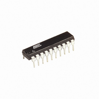
ATTINY26-16PU Atmel, ATTINY26-16PU Datasheet - Page 16

ATTINY26-16PU
Manufacturer Part Number
ATTINY26-16PU
Description
IC AVR MCU 2K 16MHZ IND 20-DIP
Manufacturer
Atmel
Series
AVR® ATtinyr
Specifications of ATTINY26-16PU
Core Processor
AVR
Core Size
8-Bit
Speed
16MHz
Connectivity
USI
Peripherals
Brown-out Detect/Reset, POR, PWM, WDT
Number Of I /o
16
Program Memory Size
2KB (1K x 16)
Program Memory Type
FLASH
Eeprom Size
128 x 8
Ram Size
128 x 8
Voltage - Supply (vcc/vdd)
4.5 V ~ 5.5 V
Data Converters
A/D 11x10b
Oscillator Type
Internal
Operating Temperature
-40°C ~ 85°C
Package / Case
20-DIP (0.300", 7.62mm)
Processor Series
ATTINY2x
Core
AVR8
Data Bus Width
8 bit
Data Ram Size
128 B
Interface Type
2-Wire/ISP/SM-Bus/SPI/UART/USI
Maximum Clock Frequency
16 MHz
Number Of Programmable I/os
16
Number Of Timers
2
Operating Supply Voltage
4.5 V to 5.5 V
Maximum Operating Temperature
+ 85 C
Mounting Style
Through Hole
3rd Party Development Tools
EWAVR, EWAVR-BL
Development Tools By Supplier
ATAVRDRAGON, ATSTK500, ATSTK600, ATAVRISP2, ATAVRONEKIT
Minimum Operating Temperature
- 40 C
On-chip Adc
11-ch x 10-bit
Package
20PDIP
Device Core
AVR
Family Name
ATtiny
Maximum Speed
16 MHz
For Use With
ATSTK600 - DEV KIT FOR AVR/AVR32770-1007 - ISP 4PORT ATMEL AVR MCU SPI/JTAGATAVRISP2 - PROGRAMMER AVR IN SYSTEMATSTK505 - ADAPTER KIT FOR 14PIN AVR MCU
Lead Free Status / RoHS Status
Lead free / RoHS Compliant
Rev. 1477D-05/03
Rev. 1477C-09/02
Rev. 1477B-04/02
Rev. 1477A-03/02
16
ATtiny26(L)
6. Updated DC Characteristics for V
7. Updated V
8. Added Figure 106 in “Pin Driver Strength” on page 146, Figure 120, Figure 121 and
9. Removed LPM Rd, Z+ from “Instruction Set Summary” on page 169. This instruction
1. Updated “Packaging Information” on page 172.
2. Removed ADHSM from “ADC Characteristics” on page 129.
3. Added section “EEPROM Write During Power-down Sleep Mode” on page 20.
4. Added section “Default Clock Source” on page 26.
5. Corrected PLL Lock value in the “Bit 0 – PLOCK: PLL Lock Detector” on page 73.
6. Added information about conversion time when selecting differential channels on
7. Corrected {DDxn, PORTxn} value on page 42.
8. Added section “Unconnected Pins” on page 46.
9. Added note for RSTDISBL Fuse in Table 50 on page 108.
10. Corrected DATA value in Figure 61 on page 116.
11. Added WD_FUSE period in Table 60 on page 123.
12. Updated “ADC Characteristics” on page 129 and added Table 66, “ADC Characteris-
13. Updated “ATtiny26 Typical Characteristics” on page 131.
14. Added LPM Rd, Z and LPM Rd, Z+ in “Instruction Set Summary” on page 169.
1. Changed the Endurance on the Flash to 10,000 Write/Erase Cycles.
1. Removed all references to Power Save sleep mode in the section “System Clock and
2. Updated the section “Analog to Digital Converter” on page 94 with more details on
3. Updated “Ordering Information” on page 171 and added QFN/MLF package
1. Initial version.
Characteristics” on page 126.
Fixed typo in “Absolute Accuracy” on page 130.
Figure 122 in “BOD Thresholds and Analog Comparator Offset” on page 155. Updated
Figure 117 and Figure 118.
is not supported in ATtiny26.
page 97.
tics, Differential Channels, T
Clock Options” on page 23.
how to read the conversion result for both differential and single-ended conversion.
information.
INT
, INL and Gain Error in “ADC Characteristics” on page 129 and page 130.
A
= -40°C to +85°C,” on page 130.
OL
, I
IL
, I
IH
, I
CC
Power Down and
V
ACIO
1477KS–AVR–08/10
in “Electrical


