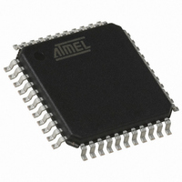
AT89C51CC03CA-RLTUM Atmel, AT89C51CC03CA-RLTUM Datasheet - Page 168

AT89C51CC03CA-RLTUM
Manufacturer Part Number
AT89C51CC03CA-RLTUM
Description
IC 8051 MCU 64K FLASH 44-VQFP
Manufacturer
Atmel
Series
AT89C CANr
Datasheet
1.AT89C51CC03C-S3RIM.pdf
(198 pages)
Specifications of AT89C51CC03CA-RLTUM
Core Processor
8051
Core Size
8-Bit
Speed
40MHz
Connectivity
CAN, UART/USART
Peripherals
POR, PWM, WDT
Number Of I /o
36
Program Memory Size
64KB (64K x 8)
Program Memory Type
FLASH
Eeprom Size
2K x 8
Ram Size
2.25K x 8
Voltage - Supply (vcc/vdd)
3 V ~ 5.5 V
Data Converters
A/D 8x10b
Oscillator Type
External
Operating Temperature
-40°C ~ 85°C
Package / Case
44-TQFP, 44-VQFP
Processor Series
AT89x
Core
8051
Data Bus Width
8 bit
Data Ram Size
2304 B
Interface Type
UART, SPI
Maximum Clock Frequency
60 MHz
Number Of Programmable I/os
36
Number Of Timers
2
Operating Supply Voltage
3 V to 5.5 V
Maximum Operating Temperature
+ 85 C
Mounting Style
SMD/SMT
3rd Party Development Tools
PK51, CA51, A51, ULINK2
Minimum Operating Temperature
- 40 C
On-chip Adc
10 bit, 8 Channel
Package
44VQFP
Device Core
8051
Family Name
AT89
Maximum Speed
60 MHz
For Use With
AT89OCD-01 - USB EMULATOR FOR AT8XC51 MCU
Lead Free Status / RoHS Status
Lead free / RoHS Compliant
Available stocks
Company
Part Number
Manufacturer
Quantity
Price
Company:
Part Number:
AT89C51CC03CA-RLTUM
Manufacturer:
ADI
Quantity:
141
Electrical Characteristics
Absolute Maximum Ratings
ICCOP Test Conditions
Power Consumption
Management
DC Parameters for Standard Voltage
Industrial T
Automotive T
V
V
Table 116. DC Parameters in Standard Voltage
168
Ambiant Temperature Under Bias:
I = industrial........................................................-40°C to 85°C
A = automotive..................................................-40°C to +125°C
Voltage on V
Voltage on Any Pin from V
Power Dissipation .............................................................. 1 W
CC
CC
Symbol
V
V
=3.0V to 5.5V and F = 0 to 40 MHz (both internal and external code execution)
=4.5V to 5.5V and F = 0 to 60 MHz (internal code execution only)
V
V
V
OL1
IH1
OL
IH
IL
AT89C51CC03
A
Parameter
Input Low Voltage
Input High Voltage except XTAL1, RST
Input High Voltage, XTAL1, RST
Output Low Voltage, ports 1, 2, 3 and 4
Output Low Voltage, port 0, ALE, PSEN
CC
= -40°C to +85°C; V
A
= -40°C to +125°C; V
from V
SS
......................................-0.5V to + 6V
SS
..................... -0.5V to V
SS
Since the introduction of the first C51 device, every manufacturer made operating I
measurements under Reset, which made sense for the designs where the CPU was
running under reset. In our new devices, the CPU is no longer active during reset, so the
power consumption is very low but not representative of what will happen in the cus-
tomer system. Thus, while keeping measurements under Reset, we present a new way
to measure the operating I
Using an internal test ROM, the following code is executed.
Label: SJMP Label (80FE)
Ports 1 and 4 are disconnected, RST = Vcc, XTAL2 is not connected and XTAL1 is
driven by the clock.
This is much more representative of the real operating Icc.
= 0V;
SS
= 0V
(6)
(6)
CC
+ 0.2V
0.2 V
0.7 V
Min
-0.5
CC
Note:
CC
+ 0.9
CC
.
Stresses at or above those listed under “Absolute Maximum
Ratings” may cause permanent damage to the device. This
is a stress rating only and functional operation of the device
at these or any other conditions above those indicated in
the operational sections of this specification is not implied.
Exposure to absolute maximum rating conditions may affect
device reliability.
The power dissipation is based on the maximum allowable
die temperature and the thermal resistance of the package.
Typ
(5)
0.2Vcc - 0.1
V
V
CC
CC
Max
0.45
0.45
0.3
1.0
0.3
1.0
+ 0.5
+ 0.5
Unit
V
V
V
V
V
V
V
V
V
I
I
I
I
I
I
OL
OL
OL
OL
OL
OL
4182O–CAN–09/08
= 100 μA
= 1.6 mA
= 3.5 mA
= 200 μA
= 3.2 mA
= 7.0 mA
Test Conditions
(4)
(4)
(4)
(4)
(4)
(4)
CC


