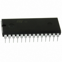
ST62T65CB6 STMicroelectronics, ST62T65CB6 Datasheet - Page 48

ST62T65CB6
Manufacturer Part Number
ST62T65CB6
Description
IC MCU 8BIT W/ADC 28-PDIP
Manufacturer
STMicroelectronics
Series
ST6r
Datasheet
1.ST62T55CB6.pdf
(84 pages)
Specifications of ST62T65CB6
Core Processor
ST6
Core Size
8-Bit
Speed
8MHz
Connectivity
SPI
Peripherals
LED, LVD, POR, WDT
Number Of I /o
21
Program Memory Size
3.8KB (3.8K x 8)
Program Memory Type
OTP
Eeprom Size
128 x 8
Ram Size
128 x 8
Voltage - Supply (vcc/vdd)
3 V ~ 6 V
Data Converters
A/D 13x8b
Oscillator Type
Internal
Operating Temperature
-40°C ~ 85°C
Package / Case
28-DIP (0.600", 15.24mm)
Processor Series
ST62T6x
Core
ST6
Data Bus Width
8 bit
Data Ram Size
128 B
Interface Type
SCI
Maximum Clock Frequency
8 MHz
Number Of Programmable I/os
21
Number Of Timers
1
Operating Supply Voltage
3 V to 6 V
Maximum Operating Temperature
+ 125 C
Mounting Style
Through Hole
Development Tools By Supplier
ST62GP-EMU2, ST62E2XC-EPB/110, ST62E6XC-EPB/US, STREALIZER-II
Minimum Operating Temperature
- 40 C
On-chip Adc
8 bit
Lead Free Status / RoHS Status
Lead free / RoHS Compliant
Available stocks
Company
Part Number
Manufacturer
Quantity
Price
Company:
Part Number:
ST62T65CB6
Manufacturer:
BOURNS
Quantity:
12 000
ST6255C ST6265C ST6265B
AUTO-RELOAD TIMER (Cont’d)
Capture Mode with PWM Generation. In this
mode, the AR counter operates as a free running
8-bit counter fed by the prescaler output. The
counter is incremented on every clock rising edge.
An 8-bit capture operation from the counter to the
ARRC register is performed on every active edge
on the ARTIMin pin, when enabled by Edge Con-
trol bits SL0, SL1 in the ARSC1 register. At the
same time, the External Flag, EF, in the ARSC0
register is set and an external interrupt request is
generated if the External Interrupt Enable bit, EIE,
in the ARMC register, is set. The EF flag must be
reset by user software.
Each ARTC overflow sets ARTIMout, while a
match between the counter and ARCP (Compare
Register) resets ARTIMout and sets the compare
flag, CPF. A compare interrupt request is generat-
ed if the related compare interrupt enable bit,
CPIE, is set. A PWM signal is generated on ARTI-
Mout. The CPF flag must be reset by user soft-
ware.
The frequency of the generated signal is deter-
mined by the prescaler setting. The duty cycle is
determined by the ARCP register.
Initialization and reading of the counter are identi-
cal to the auto-reload mode (see previous descrip-
tion).
Enabling and selection of clock sources is control-
led by the CC0 and CC1 bits in the AR Status Con-
trol Register, ARSC1.
The prescaler division ratio is selected by pro-
gramming the PS0, PS1 and PS2 bits in the
ARSC1 Register.
In Capture mode, the allowed clock sources are
the internal clock and the internal clock divided by
3; the external ARTIMin input pin should not be
used as a clock source.
Capture Mode with Reset of counter and pres-
caler, and PWM Generation. This mode is identi-
cal to the previous one, with the difference that a
capture condition also resets the counter and the
prescaler, thus allowing easy measurement of the
time between two captures (for input period meas-
urement on the ARTIMin pin).
Note: In this mode it is recommended not to
change the ARTimer counter value from FFH to
any other value by writing this value in the ARRC
register and setting the TLCD bit in the ARMC reg-
ister.
48/84
Load on External Input. The counter operates as
a free running 8-bit counter fed by the prescaler.
the count is incremented on every clock rising
edge.
Each counter overflow sets the ARTIMout pin. A
match between the counter and ARCP (Compare
Register) resets the ARTIMout pin and sets the
compare flag, CPF. A compare interrupt request is
generated if the related compare interrupt enable
bit, CPIE, is set. A PWM signal is generated on
ARTIMout. The CPF flag must be reset by user
software.
Initialization of the counter is as described in the
previous paragraph. In addition, if the external AR-
TIMin input is enabled, an active edge on the input
pin will copy the contents of the ARRC register into
the counter, whether the counter is running or not.
Notes:
The allowed AR Timer clock sources are the fol-
lowing:
The clock frequency should not be modified while
the counter is counting, since the counter may be
set to an unpredictable value. For instance, the
multiplexer setting should not be modified while
the counter is counting.
Loading of the counter by any means (by auto-re-
load, through ARLR, ARRC or by the Core) resets
the prescaler at the same time.
Care should be taken when both the Capture inter-
rupt and the Overflow interrupt are used. Capture
and overflow are asynchronous. If the capture oc-
curs when the Overflow Interrupt Flag, OVF, is
high (between counter overflow and the flag being
reset by software, in the interrupt routine), the Ex-
ternal Interrupt Flag, EF, may be cleared simul-
taneusly without the interrupt being taken into ac-
count.
The solution consists in resetting the OVF flag by
writing 06h in the ARSC0 register. The value of EF
is not affected by this operation. If an interrupt has
occured, it will be processed when the MCU exits
from the interrupt routine (the second interrupt is
latched).
Auto-reload mode
Capture mode
Capture/Reset mode
External Load mode
AR Timer Mode
f
f
f
f
INT
INT
INT
INT
, f
, f
, f
, f
INT/3
INT/3
INT/3
INT/3
Clock Sources
, ARTIMin


