ST62T65CB6 STMicroelectronics, ST62T65CB6 Datasheet - Page 49
ST62T65CB6
Manufacturer Part Number
ST62T65CB6
Description
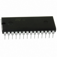
IC MCU 8BIT W/ADC 28-PDIP
Manufacturer
STMicroelectronics
Series
ST6r
Datasheet
1.ST62T55CB6.pdf
(84 pages)
Specifications of ST62T65CB6
Core Processor
ST6
Core Size
8-Bit
Speed
8MHz
Connectivity
SPI
Peripherals
LED, LVD, POR, WDT
Number Of I /o
21
Program Memory Size
3.8KB (3.8K x 8)
Program Memory Type
OTP
Eeprom Size
128 x 8
Ram Size
128 x 8
Voltage - Supply (vcc/vdd)
3 V ~ 6 V
Data Converters
A/D 13x8b
Oscillator Type
Internal
Operating Temperature
-40°C ~ 85°C
Package / Case
28-DIP (0.600", 15.24mm)
Processor Series
ST62T6x
Core
ST6
Data Bus Width
8 bit
Data Ram Size
128 B
Interface Type
SCI
Maximum Clock Frequency
8 MHz
Number Of Programmable I/os
21
Number Of Timers
1
Operating Supply Voltage
3 V to 6 V
Maximum Operating Temperature
+ 125 C
Mounting Style
Through Hole
Development Tools By Supplier
ST62GP-EMU2, ST62E2XC-EPB/110, ST62E6XC-EPB/US, STREALIZER-II
Minimum Operating Temperature
- 40 C
On-chip Adc
8 bit
Lead Free Status / RoHS Status
Lead free / RoHS Compliant
Available stocks
Company
Part Number
Manufacturer
Quantity
Price
Company:

Part Number:
ST62T65CB6
Manufacturer:
BOURNS
Quantity:
12 000


AUTO-RELOAD TIMER (Cont’d)
4.3.3 AR Timer Registers
AR Mode Control Register (ARMC)
Address: D5h — Read/Write
Reset status: 00h
The AR Mode Control Register ARMC is used to
program the different operating modes of the AR
Timer, to enable the clock and to initialize the
counter. It can be read and written to by the Core
and it is cleared on system reset (the AR Timer is
disabled).
Note: Care should be taken when writing to the
ARMC register while AR Timer is running: if a
PWM signal is being output while the ARMC regis-
ter is overwritten with its previous value, ARTIMout
pin remains at its previous state for a programmed
time equal to t
new count starts.
Bit 7 = TLCD: Timer Load Bit. This bit, when set,
will cause the contents of ARRC register to be
loaded into the counter and the contents of the
prescaler register, ARPSC, are cleared in order to
initialize the timer before starting to count. This bit
is write-only and any attempt to read it will yield a
logical zero.
Bit 6 = TEN: Timer Clock Enable. This bit, when
set, allows the timer to count. When cleared, it will
stop the timer and freeze ARPSC and ARTSC.
Bit 5 = PWMOE: PWM Output Enable. This bit,
when set, enables the PWM output on the ARTI-
Mout pin. When reset, the PWM output is disabled.
Bit 4 = EIE: External Interrupt Enable. This bit,
when set, enables the external interrupt request.
When reset, the external interrupt request is
masked. If EIE is set and the related flag, EF, in
the ARSC0 register is also set, an interrupt re-
quest is generated.
Bit 3 = CPIE: Compare Interrupt Enable. This bit,
when set, enables the compare interrupt request.
If CPIE is reset, the compare interrupt request is
masked. If CPIE is set and the related flag, CPF, in
the ARSC0 register is also set, an interrupt re-
quest is generated.
TCLD
7
TEN
PWMOE
HIGH
(refer to
EIE
CPIE
Figure
OVIE ARMC1 ARMC0
28). Then, a
0
Bit 2 = OVIE: Overflow Interrupt. This bit, when
set, enables the overflow interrupt request. If OVIE
is reset, the compare interrupt request is masked.
If OVIE is set and the related flag, OVF in the
ARSC0 register is also set, an interrupt request is
generated.
Bit 1-0 = ARMC1-ARMC0: Mode Control Bits 1-0.
These are the operating mode control bits. The fol-
lowing bit combinations will select the various op-
erating modes:
AR Timer Status/Control Registers ARSC0 &
ARSC1. These registers contain the AR Timer sta-
tus information bits and also allow the program-
ming of clock sources, active edge and prescaler
multiplexer setting.
ARSC0 register bits 0,1 and 2 contain the interrupt
flags of the AR Timer. These bits are read normal-
ly. Each one may be reset by software. Writing a
one does not affect the bit value.
AR Status Control Register 0 (ARSC0)
Address: D6h — Read/Clear
Bits 7-3 = D7-D3: Unused
Bit 2 = EF: External Interrupt Flag. This bit is set by
any active edge on the external ARTIMin input pin.
The flag is cleared by writing a zero to the EF bit.
Bit 1 = CPF: Compare Interrupt Flag. This bit is set
if the contents of the counter and the ARCP regis-
ter are equal. The flag is cleared by writing a zero
to the CPF bit.
Bit 0 = OVF: Overflow Interrupt Flag. This bit is set
by a transition of the counter from FFh to 00h
(overflow). The flag is cleared by writing a zero to
the OVF bit.
D7
7
ARMC1
0
0
1
1
D6
D5
ARMC0
ST6255C ST6265C ST6265B
0
1
0
1
D4
Auto-reload Mode
Capture Mode
Capture Mode with Reset
of ARTC and ARPSC
Load on External Edge
Mode
D3
Operating Mode
EF
CPF
OVF
49/84
0
Related parts for ST62T65CB6
Image
Part Number
Description
Manufacturer
Datasheet
Request
R

Part Number:
Description:
STMicroelectronics [RIPPLE-CARRY BINARY COUNTER/DIVIDERS]
Manufacturer:
STMicroelectronics
Datasheet:
Part Number:
Description:
STMicroelectronics [LIQUID-CRYSTAL DISPLAY DRIVERS]
Manufacturer:
STMicroelectronics
Datasheet:

Part Number:
Description:
BOARD EVAL FOR MEMS SENSORS
Manufacturer:
STMicroelectronics
Datasheet:
Part Number:
Description:
NPN TRANSISTOR POWER MODULE
Manufacturer:
STMicroelectronics
Datasheet:
Part Number:
Description:
TURBOSWITCH ULTRA-FAST HIGH VOLTAGE DIODE
Manufacturer:
STMicroelectronics
Datasheet:
Part Number:
Description:
Manufacturer:
STMicroelectronics
Datasheet:
Part Number:
Description:
DIODE / SCR MODULE
Manufacturer:
STMicroelectronics
Datasheet:
Part Number:
Description:
DIODE / SCR MODULE
Manufacturer:
STMicroelectronics
Datasheet:
Part Number:
Description:
Search -----> STE16N100
Manufacturer:
STMicroelectronics
Datasheet:
Part Number:
Description:
Search ---> STE53NA50
Manufacturer:
STMicroelectronics
Datasheet:
Part Number:
Description:
NPN Transistor Power Module
Manufacturer:
STMicroelectronics
Datasheet:
Part Number:
Description:
DIODE / SCR MODULE
Manufacturer:
STMicroelectronics
Datasheet: