ST62T65CB6 STMicroelectronics, ST62T65CB6 Datasheet - Page 55
ST62T65CB6
Manufacturer Part Number
ST62T65CB6
Description
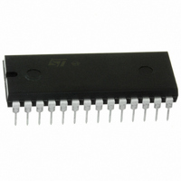
IC MCU 8BIT W/ADC 28-PDIP
Manufacturer
STMicroelectronics
Series
ST6r
Datasheet
1.ST62T55CB6.pdf
(84 pages)
Specifications of ST62T65CB6
Core Processor
ST6
Core Size
8-Bit
Speed
8MHz
Connectivity
SPI
Peripherals
LED, LVD, POR, WDT
Number Of I /o
21
Program Memory Size
3.8KB (3.8K x 8)
Program Memory Type
OTP
Eeprom Size
128 x 8
Ram Size
128 x 8
Voltage - Supply (vcc/vdd)
3 V ~ 6 V
Data Converters
A/D 13x8b
Oscillator Type
Internal
Operating Temperature
-40°C ~ 85°C
Package / Case
28-DIP (0.600", 15.24mm)
Processor Series
ST62T6x
Core
ST6
Data Bus Width
8 bit
Data Ram Size
128 B
Interface Type
SCI
Maximum Clock Frequency
8 MHz
Number Of Programmable I/os
21
Number Of Timers
1
Operating Supply Voltage
3 V to 6 V
Maximum Operating Temperature
+ 125 C
Mounting Style
Through Hole
Development Tools By Supplier
ST62GP-EMU2, ST62E2XC-EPB/110, ST62E6XC-EPB/US, STREALIZER-II
Minimum Operating Temperature
- 40 C
On-chip Adc
8 bit
Lead Free Status / RoHS Status
Lead free / RoHS Compliant
Available stocks
Company
Part Number
Manufacturer
Quantity
Price
Company:

Part Number:
ST62T65CB6
Manufacturer:
BOURNS
Quantity:
12 000


SERIAL PERIPHERAL INTERFACE SPI (Cont’d)
SPI DIV Register (DIV)
Address: E1h — Read/Write
Reset status: 00h
The SPIDIV register defines the transmission rate
and frame format and contains the interrupt flag.
Bits CD0-CD2, DIV3-DIV6 are read/write while
SPINT can be read and cleared only. Write access
is not allowed if SPRUN in the MOD register is set.
Bit 7 = SPINT: Interrupt Flag. If SPIE bit=1, SPINT
is automatically set to one by the SPI at the end of
a transmission or reception and an interrupt re-
quest can be generated depending on the state of
the interrupt mask bit in the MOD control register.
This bit is write and read and must be cleared by
user software at the end of the interrupt service
routine.
Bit 6-3 = DIV6-DIV3: Burst Mode Bit Clock Period
Selection. Define the number of shift register bits
that are transmitted or received in a frame. The
available selections are listed in
normal maximum setting is 8 bits, since the shift
register is 8 bits wide. Note that by setting a great-
er number of bits, in conjunction with the SPIN bit
in the MOD register, unwanted data bits may be fil-
tered from the data stream.
Bit 2-0 = CD2-CD0: Base/Bit Clock Rate Selec-
tion. Define the division ratio between the core
clock (f
the Shift Register in Master mode.
Table 16. Base/Bit Clock Ratio Selection
Note: For example, when an 8MHz CPU clock is
used, asynchronous operation at 9600 Baud is
possible (8MHz/13/64). Other Baud rates are
available by proportionally selecting division fac-
tors depending on CPU clock frequency.
Data setup time on Sin is typically 250ns min, while
data hold time is typically 50ns min.
0
0
0
0
1
1
1
1
SPINT
7
CD2-CD0
INT
DOV6
0
0
1
1
0
0
1
1
divided by 13) and the clock supplied to
DIV5
0
1
0
1
0
1
0
1
DIV4
Divide by 1
Divide by 2
Divide by 4
Divide by 8
Divide by 16
Divide by 32
Divide by 64
Divide by 256
Divide Ratio (decimal)
DIV3
CD2
Table
CD1
17. The
CD0
0
Table 17. Burst Mode Bit Clock Periods
SPI Data/Shift Register (SPIDSR)
Address: E0h — Read/Write
Reset status: XXh
SPIDSR is read/write, however write access is not
allowed if the SPRUN bit of Mode Control register
is set to one.
Data is sampled into SPDSR on the SCK edge de-
termined by the CPOL and CPHA bits. The affect
of these setting is shown in the following diagrams.
The Shift Register transmits and receives the Most
Significant Bit first.
Bit 7-0 = DSR7-DSR0: Data Bits. These are the
SPI shift register data bits.
Miscellaneous Register (MISCR)
Address: DDh — Write only
Reset status: xxxxxxxb
Bit 7-1 = D7-D1: Reserved.
Bit 0 = D0: Bit 0. This bit, when set, selects the
Sout pin as the SPI output line. When this bit is
cleared, Sout acts as a standard I/O line.
0
0
0
0
0
0
0
0
1
1
1
1
1
1
1
1
D7
7
7
-
DIV6-DIV3
0
0
0
0
1
1
1
1
0
0
0
0
1
1
1
1
D6
-
0
0
1
1
0
0
1
1
0
0
1
1
0
0
1
1
D5
-
ST6255C ST6265C ST6265B
0
1
0
1
0
1
0
1
0
1
0
1
0
1
0
1
D4
-
1
2
3
4
5
6
7
8
9
10
11
12
13
14
15
Reserved (not to be used)
Number of bits sent
D3
-
Refer to the
description of the
DIV6-DIV3 bits in
the DIV Register
D2
-
D1
-
55/84
D0
D0
0
0
Related parts for ST62T65CB6
Image
Part Number
Description
Manufacturer
Datasheet
Request
R

Part Number:
Description:
STMicroelectronics [RIPPLE-CARRY BINARY COUNTER/DIVIDERS]
Manufacturer:
STMicroelectronics
Datasheet:
Part Number:
Description:
STMicroelectronics [LIQUID-CRYSTAL DISPLAY DRIVERS]
Manufacturer:
STMicroelectronics
Datasheet:

Part Number:
Description:
BOARD EVAL FOR MEMS SENSORS
Manufacturer:
STMicroelectronics
Datasheet:
Part Number:
Description:
NPN TRANSISTOR POWER MODULE
Manufacturer:
STMicroelectronics
Datasheet:
Part Number:
Description:
TURBOSWITCH ULTRA-FAST HIGH VOLTAGE DIODE
Manufacturer:
STMicroelectronics
Datasheet:
Part Number:
Description:
Manufacturer:
STMicroelectronics
Datasheet:
Part Number:
Description:
DIODE / SCR MODULE
Manufacturer:
STMicroelectronics
Datasheet:
Part Number:
Description:
DIODE / SCR MODULE
Manufacturer:
STMicroelectronics
Datasheet:
Part Number:
Description:
Search -----> STE16N100
Manufacturer:
STMicroelectronics
Datasheet:
Part Number:
Description:
Search ---> STE53NA50
Manufacturer:
STMicroelectronics
Datasheet:
Part Number:
Description:
NPN Transistor Power Module
Manufacturer:
STMicroelectronics
Datasheet:
Part Number:
Description:
DIODE / SCR MODULE
Manufacturer:
STMicroelectronics
Datasheet: