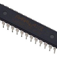
PBASIC2SX/P Parallax Inc, PBASIC2SX/P Datasheet

BASIC STAMP 2SX INTERPRETER CHIP

PBASIC2SX/P

Manufacturer Part Number
PBASIC2SX/P
Description
BASIC STAMP 2SX INTERPRETER CHIP
Manufacturer
Parallax Inc
Datasheet

Specifications of PBASIC2SX/P

Program Memory Type
EEPROM
Operating Supply Voltage
3 V to 5 V
Maximum Operating Temperature
+ 85 C
Mounting Style
Through Hole
Package / Case
DIP-28
For Use With
28803 - KIT BOARD OF EDU W/O PWR SUPP28300 - MOTHERBOARD BASIC STAMP 2PE28150 - BOARD OF EDUCATION28103 - KIT FULL BOARD OF EDUCATION
Lead Free Status / Rohs Status
 Details
Other names
PBASIC2SX-28/DP
OEM BS2sx - Rev A
1. The two lowest profile components on the board are the 4.7K
2. The next lowest profile component on the board is the 20-pin
3. Next, find the two 0.1 uF ceramic capacitors. Like, the resistors, it doesn’t matter
4. The next component to look for is a small capacitor like C2 and C3 except that this one is a
5. Next, find the resistor networks. A resistor network looks like
6. The IC sockets are next in line. Nearly all ICs have a ‘Pin 1’
sales / technical support (916) 624-8333 fax (916) 624-8003
email: stamptech@parallaxinc.com
Ohm resistors. These resistors should have color bands around
them which signify their value. The color band pattern should be: Yellow, Violet, Red, and
Gold. Resistors are polarity insensitive, which means that it doesn’t matter which end goes
where. Install the resistors where designated by ‘R1’ and ‘R2’.
right angle strip header. It may seem ambigious as to which side
is inserted into the pcb. The side with the angle should be
inserted into the pcb as shown in the drawing to the right. Install
the strip header where designated by ‘X1’.
which way these are installed. Install the two capacitors where designated by ‘C2’
and ‘C3’.
5pF capacitor and is marked with a ‘5’. Install this capacitor where designated by ‘C4’.
a comb for a ‘Barbie Doll’. On the resistor network (Rnet),
there is a dot printed near one end to signify at which end Pin
1 is located. Find Pin 1 on the Rnet and correlate it to the
square pad on the PCB
designator. Install the Rnets where designated by ‘RN1’ and ‘RN2’.
marker that denotes the location of Pin 1. It is important to
install chips with the proper orientation since, more often
than not, installing a chip backwards will result in damage to
the chip and/or surrounding circuitry. For the IC sockets that
you will be installing, there is a notch on the edge of one of
the short sides. This notch denotes the ‘top’ of the chip.
When oriented properly, Pin 1 is the top-left pin as depicted
in the drawing to the right. Install both the 28-Pin and the 8-
Pin DIP sockets into U1 and U2 respectively.
This document is a guide that will aid you in the assembly of your
OEM-BS2sx. It is assumed that you have the proper equipment,
and possess the skills necessary to safely assemble electronic
components.
Generally, it is best to start with the lower profile components, and
then work your way to the tallest components. This is often true
because, in tight places, lower profile components are more
difficult to get to with taller components in the way.
that pertains to the ‘RN1’ part
Assembly Instructions
OEM BS2sx
Rev 1.0
Page 1

Related parts for PBASIC2SX/P

PBASIC2SX/P Summary of contents

Page 1

OEM BS2sx - Rev A This document is a guide that will aid you in the assembly of your OEM-BS2sx assumed that you have the proper equipment, and possess the skills necessary to safely assemble electronic components. Generally, ...

Page 2

The next component to install is the ceramic resonator. The ceramic resonator looks like a coffee bean (although sometimes they are blue instead of brown) with three metal legs sticking out from one side and should be marked as ...

Page 3

OEM BS2sx – Rev A One of the main purposes behind the OEM BS2sx is making it easier to embed a BS2sx into an OEM design. When designing the BS2sx into an your product, please consider the following: Power Supply ...

Page 4

The above images of the board layers are not to scale. Please visit actual source and gerber files. This board was designed using Protel’s Client ’98 software. The top copper layer is the center plot, and the bottom copper layer ...

Page 5

OEM BS2sx - Rev A This document is a guide that will aid you in the assembly of your OEM-BS2sx assumed that you have the proper equipment, and possess the skills necessary to safely assemble electronic components. Generally, ...

Page 6

The next component to install is the ceramic resonator. The ceramic resonator looks like a coffee bean (although sometimes they are blue instead of brown) with three metal legs sticking out from one side and should be marked as ...

Page 7

OEM BS2sx – Rev A One of the main purposes behind the OEM BS2sx is making it easier to embed a BS2sx into an OEM design. When designing the BS2sx into an your product, please consider the following: Power Supply ...

Page 8

The above images of the board layers are not to scale. Please visit actual source and gerber files. This board was designed using Protel’s Client ’98 software. The top copper layer is the center plot, and the bottom copper layer ...

Related keywords