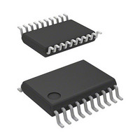
R5F21324CNSP#U0 Renesas Electronics America, R5F21324CNSP#U0 Datasheet - Page 19

R5F21324CNSP#U0
Manufacturer Part Number
R5F21324CNSP#U0
Description
MCU 1KB FLASH 16K ROM 20-LSSOP
Manufacturer
Renesas Electronics America
Series
R8C/3x/32Cr
Datasheet
1.R5F21321CDSPU0.pdf
(605 pages)
Specifications of R5F21324CNSP#U0
Core Processor
R8C
Core Size
16/32-Bit
Speed
20MHz
Connectivity
I²C, LIN, SIO, SSU, UART/USART
Peripherals
POR, PWM, Voltage Detect, WDT
Number Of I /o
15
Program Memory Size
16KB (16K x 8)
Program Memory Type
FLASH
Ram Size
1.5K x 8
Voltage - Supply (vcc/vdd)
1.8 V ~ 5.5 V
Data Converters
A/D 4x10b
Oscillator Type
Internal
Operating Temperature
-20°C ~ 85°C
Package / Case
20-LSSOP
Lead Free Status / RoHS Status
Lead free / RoHS Compliant
Eeprom Size
-
- Current page: 19 of 605
- Download datasheet (6Mb)
23.
24.
25.
22.6
22.7
23.1
24.1
24.2
24.3
24.4
24.5
24.6
25.1
25.2
22.5.5
22.5.6
22.5.7
22.6.1
22.6.2
22.6.3
22.7.1
22.7.2
24.2.1
24.2.2
24.2.3
24.2.4
24.2.5
24.2.6
24.2.7
24.2.8
24.2.9
24.2.10 SS Status Register (SSSR) ................................................................................................................ 369
24.2.11 SS Mode Register 2 (SSMR2) .......................................................................................................... 370
24.3.1
24.3.2
24.3.3
24.3.4
24.4.1
24.4.2
24.4.3
24.5.1
24.5.2
24.5.3
24.5.4
25.2.1
25.2.2
Clock Synchronous Serial Interface ............................................................................................ 360
Synchronous Serial Communication Unit (SSU) ........................................................................ 361
I
2
C bus Interface ......................................................................................................................... 391
Multiprocessor Communication Function ............................................................................................. 351
Notes on Serial Interface (UART2) ....................................................................................................... 358
Mode Selection ...................................................................................................................................... 360
Overview ............................................................................................................................................... 361
Registers ................................................................................................................................................ 363
Common Items for Multiple Modes ...................................................................................................... 371
Clock Synchronous Communication Mode .......................................................................................... 376
Operation in 4-Wire Bus Communication Mode .................................................................................. 383
Notes on Synchronous Serial Communication Unit .............................................................................. 390
Overview ............................................................................................................................................... 391
Registers ................................................................................................................................................ 394
SDA Input ......................................................................................................................................... 350
ACK and NACK ............................................................................................................................... 350
Initialization of Transmission/Reception .......................................................................................... 350
Multiprocessor Transmission ............................................................................................................ 354
Multiprocessor Reception ................................................................................................................. 355
RXD2 Digital Filter Select Function ................................................................................................ 357
Clock Synchronous Serial I/O Mode ................................................................................................ 358
Special Mode 1 (I
Module Standby Control Register (MSTCR) ................................................................................... 363
SSU/IIC Pin Select Register (SSUIICSR) ........................................................................................ 363
SS Bit Counter Register (SSBR) ...................................................................................................... 364
SS Transmit Data Register (SSTDR) ................................................................................................ 364
SS Receive Data Register (SSRDR) ................................................................................................. 365
SS Control Register H (SSCRH) ...................................................................................................... 365
SS Control Register L (SSCRL) ....................................................................................................... 366
SS Mode Register (SSMR) ............................................................................................................... 367
SS Enable Register (SSER) .............................................................................................................. 368
Transfer Clock .................................................................................................................................. 371
SS Shift Register (SSTRSR) ............................................................................................................. 373
Interrupt Requests ............................................................................................................................. 374
Communication Modes and Pin Functions ....................................................................................... 375
Initialization in Clock Synchronous Communication Mode ............................................................ 376
Data Transmission ............................................................................................................................ 377
Data Reception .................................................................................................................................. 379
Initialization in 4-Wire Bus Communication Mode ......................................................................... 384
Data Transmission ............................................................................................................................ 385
Data Reception .................................................................................................................................. 387
SCS Pin Control and Arbitration ...................................................................................................... 389
Module Standby Control Register (MSTCR) ................................................................................... 394
SSU/IIC Pin Select Register (SSUIICSR) ........................................................................................ 394
2
C Mode) .............................................................................................................. 359
A - 10
Related parts for R5F21324CNSP#U0
Image
Part Number
Description
Manufacturer
Datasheet
Request
R

Part Number:
Description:
KIT STARTER FOR M16C/29
Manufacturer:
Renesas Electronics America
Datasheet:

Part Number:
Description:
KIT STARTER FOR R8C/2D
Manufacturer:
Renesas Electronics America
Datasheet:

Part Number:
Description:
R0K33062P STARTER KIT
Manufacturer:
Renesas Electronics America
Datasheet:

Part Number:
Description:
KIT STARTER FOR R8C/23 E8A
Manufacturer:
Renesas Electronics America
Datasheet:

Part Number:
Description:
KIT STARTER FOR R8C/25
Manufacturer:
Renesas Electronics America
Datasheet:

Part Number:
Description:
KIT STARTER H8S2456 SHARPE DSPLY
Manufacturer:
Renesas Electronics America
Datasheet:

Part Number:
Description:
KIT STARTER FOR R8C38C
Manufacturer:
Renesas Electronics America
Datasheet:

Part Number:
Description:
KIT STARTER FOR R8C35C
Manufacturer:
Renesas Electronics America
Datasheet:

Part Number:
Description:
KIT STARTER FOR R8CL3AC+LCD APPS
Manufacturer:
Renesas Electronics America
Datasheet:

Part Number:
Description:
KIT STARTER FOR RX610
Manufacturer:
Renesas Electronics America
Datasheet:

Part Number:
Description:
KIT STARTER FOR R32C/118
Manufacturer:
Renesas Electronics America
Datasheet:

Part Number:
Description:
KIT DEV RSK-R8C/26-29
Manufacturer:
Renesas Electronics America
Datasheet:

Part Number:
Description:
KIT STARTER FOR SH7124
Manufacturer:
Renesas Electronics America
Datasheet:

Part Number:
Description:
KIT STARTER FOR H8SX/1622
Manufacturer:
Renesas Electronics America
Datasheet:

Part Number:
Description:
KIT DEV FOR SH7203
Manufacturer:
Renesas Electronics America
Datasheet:


