R5F21334CNFP#U0 Renesas Electronics America, R5F21334CNFP#U0 Datasheet - Page 478
R5F21334CNFP#U0
Manufacturer Part Number
R5F21334CNFP#U0
Description
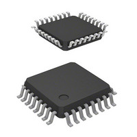
MCU 1KB FLASH 16K ROM 32-LQFP
Manufacturer
Renesas Electronics America
Series
R8C/3x/33Cr
Datasheet
1.R5F21331CNFPU0.pdf
(622 pages)
Specifications of R5F21334CNFP#U0
Core Processor
R8C
Core Size
16/32-Bit
Speed
20MHz
Connectivity
I²C, LIN, SIO, SSU, UART/USART
Peripherals
POR, PWM, Voltage Detect, WDT
Number Of I /o
27
Program Memory Size
16KB (16K x 8)
Program Memory Type
FLASH
Ram Size
1.5K x 8
Voltage - Supply (vcc/vdd)
1.8 V ~ 5.5 V
Data Converters
A/D 12x10b; D/A 2x8b
Oscillator Type
Internal
Operating Temperature
-20°C ~ 85°C
Package / Case
32-LQFP
Lead Free Status / RoHS Status
Lead free / RoHS Compliant
Eeprom Size
-
Available stocks
Company
Part Number
Manufacturer
Quantity
Price

Part Number:
R5F21334CNFP#U0R5F21334CNFP#V2
Manufacturer:
Renesas Electronics America
Quantity:
10 000


R8C/33C Group
REJ09B0570-0100 Rev.1.00 Dec. 14, 2009
Page 448 of 589
Figure 26.5
26.4.2
LINCR register
TRAIC register
LINST register
LINST register
RXDSF flag in
SBDCT flag in
SFDCT flag in
Figure 26.5 shows an Operating Example during Header Field Reception in slave mode. Figure 26.6 through
Figure 26.8 show examples of Header Field Reception Flowchart.
During header field reception, the hardware LIN operates as follows:
(1) When 1 is written to the LSTART bit in the LINCR register for the hardware LIN, Synch Break detection is
(2) If a “L” level is input for a duration equal to or longer than the period set in timer RA, the hardware LIN
(3) The hardware LINA receives a Synch Field (55h) and measures the period of the start bit and bits 0 to 6 is
(4) When the Synch Field measurement is completed, the SFDCT flag in the LINST register is set to 1. If the
(5) After the Synch Field measurement is completed, a transfer rate is calculated from the timer RA count
(6) After the hardware LIN completes receiving the ID field, it performs communication for a response field.
RXD0 input
for UART0
RXD0 pin
enabled.
detected it as a Synch Break. At this time, the SBDCT flag in the LINST register is set to 1. If the SBIE bit
in the LINCR register is set to 1, a timer RA interrupt is generated. Then the hardware LIN enters the Synch
Field measurement.
using timer RA. At this time, whether to input the Synch Field signal to RXD0 of UART0 can be selected
by the SBE bit in the LINCR register.
SFIE bit in the LINCR register is set to 1, a timer RA interrupt is generated.
value. The rate is set in UART0 and registers TRAPRE and TRA for timer RA are set again. Then the
hardware LIN receives an ID field via UART0.
IR bit in
Slave Mode
Operating Example during Header Field Reception
The above applies when:
LINE = 1, MST = 0, SBE = 1, SBIE = 1, SFIE = 1
(1)
1 is written to LSTART bit
in LINCR register.
Synch Break
(2)
(3)
This period is measured.
Set to 0 when an interrupt request is acknowledged
or by a program.
1 is written to B1CLR bit
in LINST register.
Synch Field
(4)
(5)
1 is written to B0CLR bit
in LINST register.
The flag is set to 0 after Synch Field
measurement is completed.
IDENTIFIER
(6)
26. Hardware LIN
Related parts for R5F21334CNFP#U0
Image
Part Number
Description
Manufacturer
Datasheet
Request
R

Part Number:
Description:
KIT STARTER FOR M16C/29
Manufacturer:
Renesas Electronics America
Datasheet:

Part Number:
Description:
KIT STARTER FOR R8C/2D
Manufacturer:
Renesas Electronics America
Datasheet:

Part Number:
Description:
R0K33062P STARTER KIT
Manufacturer:
Renesas Electronics America
Datasheet:

Part Number:
Description:
KIT STARTER FOR R8C/23 E8A
Manufacturer:
Renesas Electronics America
Datasheet:

Part Number:
Description:
KIT STARTER FOR R8C/25
Manufacturer:
Renesas Electronics America
Datasheet:

Part Number:
Description:
KIT STARTER H8S2456 SHARPE DSPLY
Manufacturer:
Renesas Electronics America
Datasheet:

Part Number:
Description:
KIT STARTER FOR R8C38C
Manufacturer:
Renesas Electronics America
Datasheet:

Part Number:
Description:
KIT STARTER FOR R8C35C
Manufacturer:
Renesas Electronics America
Datasheet:

Part Number:
Description:
KIT STARTER FOR R8CL3AC+LCD APPS
Manufacturer:
Renesas Electronics America
Datasheet:
Part Number:
Description:
KIT STARTER FOR RX610
Manufacturer:
Renesas Electronics America
Datasheet:

Part Number:
Description:
KIT STARTER FOR R32C/118
Manufacturer:
Renesas Electronics America
Datasheet:

Part Number:
Description:
KIT DEV RSK-R8C/26-29
Manufacturer:
Renesas Electronics America
Datasheet:

Part Number:
Description:
KIT STARTER FOR SH7124
Manufacturer:
Renesas Electronics America
Datasheet:

Part Number:
Description:
KIT STARTER FOR H8SX/1622
Manufacturer:
Renesas Electronics America
Datasheet:

Part Number:
Description:
KIT DEV FOR SH7203
Manufacturer:
Renesas Electronics America
Datasheet: