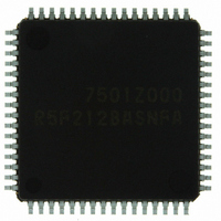
R5F212BASNFA#U0 Renesas Electronics America, R5F212BASNFA#U0 Datasheet - Page 38

R5F212BASNFA#U0
Manufacturer Part Number
R5F212BASNFA#U0
Description
IC R8C/2B MCU FLASH 96+2K 64LQFP
Manufacturer
Renesas Electronics America
Series
R8C/2x/2Br
Datasheet
1.R5F212B7SNFPU0.pdf
(66 pages)
Specifications of R5F212BASNFA#U0
Core Processor
R8C
Core Size
16/32-Bit
Speed
20MHz
Connectivity
I²C, LIN, SIO, SSU, UART/USART
Peripherals
POR, PWM, Voltage Detect, WDT
Number Of I /o
55
Program Memory Size
96KB (96K x 8)
Program Memory Type
FLASH
Ram Size
7K x 8
Voltage - Supply (vcc/vdd)
2.2 V ~ 5.5 V
Data Converters
A/D 12x10b; D/A 2x8b
Oscillator Type
Internal
Operating Temperature
-20°C ~ 85°C
Package / Case
64-LQFP
For Use With
R0K5212D8S001BE - KIT STARTER FOR R8C/2DR0K5212D8S000BE - KIT DEV FOR R8C/2D
Lead Free Status / RoHS Status
Lead free / RoHS Compliant
Eeprom Size
-
Available stocks
Company
Part Number
Manufacturer
Quantity
Price
Part Number:
R5F212BASNFA#U0R5F212BASNFA#V2
Manufacturer:
Renesas Electronics America
Quantity:
10 000
R8C/2A Group, R8C/2B Group
Rev.2.10
REJ03B0182-0210
Table 5.3
NOTES:
Table 5.4
NOTES:
−
−
R
t
V
V
−
−
−
t
R
I
conv
su
Vref
ref
IA
ladder
O
Symbol
Symbol
1. V
2. When the analog input voltage is over the reference voltage, the A/D conversion result will be 3FFh in 10-bit mode and FFh in
1. V
2. This applies when one D/A converter is used and the value of the DAi register (i = 0 or 1) for the unused D/A converter is 00h.
8-bit mode.
The resistor ladder of the A/D converter is not included. Also, even if the VCUT bit in the ADCON1 register is set to 0 (V
not connected), I
CC
CC
Nov 26, 2007
/AV
/AV
Resolution
Absolute
accuracy
Resistor ladder
Conversion time 10-bit mode
Reference voltage
Analog input voltage
A/D operating
clock frequency
Resolution
Absolute accuracy
Setup time
Output resistor
Reference power input current
CC
CC
A/D Converter Characteristics
= Vref = 2.2 to 5.5 V at T
D/A Converter Characteristics
= Vref = 2.7 to 5.5 V at T
Vref
flows into the D/A converters.
Page 36 of 60
Parameter
Parameter
10-bit mode
8-bit mode
10-bit mode
8-bit mode
10-bit mode
8-bit mode
8-bit mode
Without sample and hold
With sample and hold
Without sample and hold
With sample and hold
(2)
opr
opr
= -20 to 85°C (N version) / -40 to 85°C (D version), unless otherwise specified.
= -20 to 85°C (N version) / -40 to 85°C (D version), unless otherwise specified.
(1)
(1)
V
V
V
V
V
(NOTE 2)
φ
φ
φ
φ
φ
φ
V
φ
φ
AD
AD
AD
AD
AD
AD
AD
AD
ref
ref
ref
ref
ref
ref
= AV
= AV
= AV
= AV
= AV
= 10 MHz, V
= 10 MHz, V
= 10 MHz, V
= 10 MHz, V
= 5 MHz, V
= 5 MHz, V
= AV
= 10 MHz, V
= 10 MHz, V
CC
CC
CC
CC
CC
CC
= 2.7 to 5.5 V
= 2.7 to 5.5 V
= 2.2 to 5.5 V
= 2.2 to 5.5 V
Conditions
Conditions
ref
ref
ref
ref
ref
ref
ref
ref
= AV
= AV
= AV
= AV
= AV
= AV
= AV
= AV
CC
CC
CC
CC
CC
CC
CC
CC
= 2.2 V
= 2.2 V
= 5.0 V
= 5.0 V
= 3.3 V
= 3.3 V
= 5.0 V
= 5.0 V
Min.
0.25
0.25
Min.
3.3
2.8
2.2
5. Electrical Characteristics
10
−
−
−
−
−
−
−
0
1
1
−
−
−
4
−
Standard
Standard
Typ.
Typ.
10
−
−
−
−
−
−
−
−
−
−
−
−
−
−
−
−
−
−
−
−
AV
AV
Max.
Max.
1.0
1.5
10
±3
±2
±5
±2
±5
±2
40
10
10
20
−
−
5
5
8
3
CC
CC
MHz
MHz
MHz
MHz
LSB
LSB
LSB
LSB
LSB
LSB
Unit
Unit
mA
Bit
kΩ
Bit
kΩ
µs
µs
µs
%
V
V
REF


