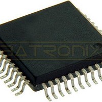
MC68HC705C9ACFBE Freescale Semiconductor, MC68HC705C9ACFBE Datasheet - Page 39

MC68HC705C9ACFBE
Manufacturer Part Number
MC68HC705C9ACFBE
Description
IC MCU 8BIT 44-QFP
Manufacturer
Freescale Semiconductor
Series
HC05r
Datasheet
1.MC705C9ACPE.pdf
(118 pages)
Specifications of MC68HC705C9ACFBE
Core Processor
HC05
Core Size
8-Bit
Speed
2.1MHz
Connectivity
SCI, SPI
Peripherals
POR, WDT
Number Of I /o
24
Program Memory Size
16KB (16K x 8)
Program Memory Type
OTP
Ram Size
352 x 8
Voltage - Supply (vcc/vdd)
3 V ~ 5.5 V
Oscillator Type
Internal
Operating Temperature
-40°C ~ 85°C
Package / Case
44-QFP
Processor Series
HC705C
Core
HC05
Data Bus Width
8 bit
Data Ram Size
352 B
Interface Type
SCI, SPI
Maximum Clock Frequency
2.1 MHz
Number Of Programmable I/os
31
Number Of Timers
1
Maximum Operating Temperature
+ 85 C
Mounting Style
SMD/SMT
Minimum Operating Temperature
- 40 C
On-chip Adc
8 bit
Package
44PQFP
Family Name
HC05
Maximum Speed
2.1 MHz
Operating Supply Voltage
3.3|5 V
Lead Free Status / RoHS Status
Lead free / RoHS Compliant
Eeprom Size
-
Data Converters
-
Lead Free Status / Rohs Status
Details
Available stocks
Company
Part Number
Manufacturer
Quantity
Price
Company:
Part Number:
MC68HC705C9ACFBE
Manufacturer:
FREESCALE
Quantity:
1 827
Company:
Part Number:
MC68HC705C9ACFBE
Manufacturer:
Freescale Semiconductor
Quantity:
10 000
Chapter 5
Resets
5.1 Introduction
The MCU can be reset four ways: by the initial power-on reset function, by an active low input to the
RESET pin, by the COP, or by the clock monitor. A reset immediately stops the operation of the instruction
being executed, initializes some control bits, and loads the program counter with a user-defined reset
vector address.
5.2 Power-On Reset (POR)
A power-on-reset occurs when a positive transition is detected on V
power turn-on conditions and should not be used to detect a drop in the power supply voltage. There is a
4064 internal processor clock cycle (t
(When configured as a C9A, the RESET pin will output a logic 0 during the 4064-cycle delay.) If the
RESET pin is low after the end of this 4064-cycle delay, the MCU will remain in the reset condition until
RESET is driven high externally.
5.3 RESET Pin
The function of the RESET pin is dependent on whether the device is configured as an MC68HC05C9A
or an MC68HC05C12A. When it is in the MC68HC05C12A configuration, the pin is input only. When in
MC68HC05C9A configuration the pin is bidirectional. In both cases the MCU is reset when a logic 0 is
applied to the RESET pin for a period of one and one-half machine cycles (t
configuration, the RESET pin will be driven low by a COP, clock monitor, or power-on reset.
Freescale Semiconductor
RESET
Figure 5-1
V
DD
MC68HC05C9A Advance Information Data Sheet, Rev. 4.1
is a block diagram of the reset sources.
STOP
POWER-ON RESET
CLOCK MONITOR
COP WATCHDOG
cyc
Figure 5-1. Reset Sources
) oscillator stabilization delay after the oscillator becomes active.
INTERNAL CLOCK
D
RESET
LATCH
R
DD
Q
. The power-on reset is strictly for
RST
RL
). For the MC68HC05C9A
TO CPU AND
SUBSYSTEMS
39


