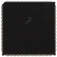
MC68HC711E9CFNE2 Freescale Semiconductor, MC68HC711E9CFNE2 Datasheet - Page 86

MC68HC711E9CFNE2
Manufacturer Part Number
MC68HC711E9CFNE2
Description
IC MCU 8BIT 512RAM 52-PLC
Manufacturer
Freescale Semiconductor
Series
HC11r
Datasheet
1.MC68HC711E9CFNE3.pdf
(336 pages)
Specifications of MC68HC711E9CFNE2
Core Processor
HC11
Core Size
8-Bit
Speed
2MHz
Connectivity
SCI, SPI
Peripherals
POR, WDT
Number Of I /o
38
Program Memory Size
12KB (12K x 8)
Program Memory Type
OTP
Eeprom Size
512 x 8
Ram Size
512 x 8
Voltage - Supply (vcc/vdd)
4.5 V ~ 5.5 V
Data Converters
A/D 8x8b
Oscillator Type
Internal
Operating Temperature
-40°C ~ 85°C
Package / Case
52-PLCC
Processor Series
HC711E
Core
HC11
Data Bus Width
8 bit
Data Ram Size
512 B
Interface Type
SCI, SPI
Maximum Clock Frequency
2 MHz
Number Of Programmable I/os
38
Number Of Timers
8
Maximum Operating Temperature
+ 85 C
Mounting Style
SMD/SMT
Minimum Operating Temperature
- 40 C
On-chip Adc
8 bit
Lead Free Status / RoHS Status
Lead free / RoHS Compliant
Available stocks
Company
Part Number
Manufacturer
Quantity
Price
Company:
Part Number:
MC68HC711E9CFNE2
Manufacturer:
TE
Quantity:
12 000
Company:
Part Number:
MC68HC711E9CFNE2
Manufacturer:
FREESCAL
Quantity:
5 530
- Current page: 86 of 336
- Download datasheet (4Mb)
Operating Modes and On-Chip Memory
4.4.3.1 System Configuration Register
Technical Data
86
NOTE:
The system configuration register (CONFIG) consists of an EEPROM
byte and static latches that control the startup configuration of the MCU.
The contents of the EEPROM byte are transferred into static working
latches during reset sequences. The operation of the MCU is controlled
directly by these latches and not by CONFIG itself. In normal modes,
changes to CONFIG do not affect operation of the MCU until after the
next reset sequence. When programming, the CONFIG register itself is
accessed. When the CONFIG register is read, the static latches are
accessed. See
Erasure
To take full advantage of the MCU’s functionality, customers can
program the CONFIG register in bootstrap mode. This can be
accomplished by setting the mode pins to logic 0 and downloading a
small program to internal RAM. For more information, Motorola
application note AN1060 entitled
included at the back of this document. The downloadable talker will
consist of:
All of this functionality is provided by PCbug11 which can be found on
the Motorola Web site at http://www.motorola.com/semiconductors/.
For more information on using PCbug11 to program an E-series device,
Motorola engineering bulletin EB296 entitled
MC68HC711E9 Devices with PCbug11 and the M68HC11EVBU
been included at the back of this document.
The CONFIG register on the 68HC11 is an EEPROM cell and must be
programmed accordingly.
Operation of the CONFIG register in the MC68HC811E2 differs from
other devices in the M68HC11 E series. See
Figure
•
•
•
Bulk erase
Byte programming
Communication server
Operating Modes and On-Chip Memory
4-11.
for information on modifying CONFIG.
4.6.1 EEPROM and CONFIG Programming and
M68HC11 Bootstrap Mode
Programming
Figure 4-10
M68HC11E Family — Rev. 3.2
and
MOTOROLA
has been
has
Related parts for MC68HC711E9CFNE2
Image
Part Number
Description
Manufacturer
Datasheet
Request
R

Part Number:
Description:
APPENDIX A ELECTRICAL CHARACTERISTICS
Manufacturer:
FREESCALE [Freescale Semiconductor, Inc]
Datasheet:
Part Number:
Description:
Manufacturer:
Freescale Semiconductor, Inc
Datasheet:
Part Number:
Description:
Manufacturer:
Freescale Semiconductor, Inc
Datasheet:
Part Number:
Description:
Manufacturer:
Freescale Semiconductor, Inc
Datasheet:
Part Number:
Description:
Manufacturer:
Freescale Semiconductor, Inc
Datasheet:
Part Number:
Description:
Manufacturer:
Freescale Semiconductor, Inc
Datasheet:
Part Number:
Description:
Manufacturer:
Freescale Semiconductor, Inc
Datasheet:
Part Number:
Description:
Manufacturer:
Freescale Semiconductor, Inc
Datasheet:
Part Number:
Description:
Manufacturer:
Freescale Semiconductor, Inc
Datasheet:
Part Number:
Description:
Manufacturer:
Freescale Semiconductor, Inc
Datasheet:
Part Number:
Description:
Manufacturer:
Freescale Semiconductor, Inc
Datasheet:
Part Number:
Description:
Manufacturer:
Freescale Semiconductor, Inc
Datasheet:
Part Number:
Description:
Manufacturer:
Freescale Semiconductor, Inc
Datasheet:
Part Number:
Description:
Manufacturer:
Freescale Semiconductor, Inc
Datasheet:
Part Number:
Description:
Manufacturer:
Freescale Semiconductor, Inc
Datasheet:


