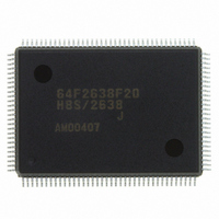
HD64F2638F20J Renesas Electronics America, HD64F2638F20J Datasheet - Page 1027

HD64F2638F20J
Manufacturer Part Number
HD64F2638F20J
Description
IC H8S MCU FLASH 256K 128-QFP
Manufacturer
Renesas Electronics America
Series
H8® H8S/2600r
Specifications of HD64F2638F20J
Core Processor
H8S/2600
Core Size
16-Bit
Speed
20MHz
Connectivity
CAN, SCI, SmartCard
Peripherals
Motor Control PWM, POR, PWM, WDT
Number Of I /o
72
Program Memory Size
256KB (256K x 8)
Program Memory Type
FLASH
Ram Size
16K x 8
Voltage - Supply (vcc/vdd)
4.5 V ~ 5.5 V
Data Converters
A/D 12x10b; D/A 2x8b
Oscillator Type
Internal
Operating Temperature
-40°C ~ 85°C
Package / Case
128-QFP
Lead Free Status / RoHS Status
Contains lead / RoHS non-compliant
Eeprom Size
-
Available stocks
Company
Part Number
Manufacturer
Quantity
Price
Company:
Part Number:
HD64F2638F20J
Manufacturer:
PENESAS
Quantity:
252
- Current page: 1027 of 1512
- Download datasheet (9Mb)
H8S/2639, H8S/2638, H8S/2636,
H8S/2630, H8S/2635 Group
23B.13 Usage Notes
1. When making a transition to subactive mode or watch mode, set the DTC to enter module stop
2. The on-chip peripheral modules (DTC and TPU) which halt operation in subactive mode
3. A 1 is always returned when an attempt is made to read the pin status of I/O ports 1, 4, 9, or F
4. Operation cannot be guaranteed if a transition is made to the subactive mode, subsleep mode,
5. (H8S/2639 Group, H8S/2635 Group only) The subclock (φSUB) is frequency divided
REJ09B0103-0800 Rev. 8.00
May 28, 2010
mode (write 1 to the relevant bits in MSTPCR), and then read the relevant bits to confirm that
they are set to 1 before mode transition. Do not clear module stop mode (write 0 to the relevant
bits in MSTPCR) until a transition from subactive mode to high-speed mode or medium-speed
mode has been performed.
If a DTC activation source occurs in subactive mode, the DTC will be activated only after
module stop mode has been cleared and high-speed mode or medium-speed mode has been
entered.
cannot clear an interrupt in subactive mode. Therefore, if a transition is made to subactive
mode while an interrupt is requested, the CPU interrupt source cannot be cleared. Disable the
interrupts of each on-chip peripheral module before executing a SLEEP instruction to enter
subactive mode or watch mode.
during operation in subactive mode. (In the case of port 1, pins 13 to 10 are readable.) In
addition, the ports may be used as output ports (except for ports 4 and 9). The procedure for
determining the pin status during operation in subactive mode is as follows.
[1] Use ports 3, A, B, C, D, E, H, and J as input ports.
[2] Use external interrupt inputs (IRQ0 to IRQ5). (If the level sense setting has been selected
or watch mode when the SUBSTP bit in LPWRCR is set to 1 (subclock generation prohibited).
To prevent problems, it should be confirmed that the SUBSTP bit has been cleared to 0 before
transitioning to the subactive mode, subsleep mode, or watch mode.
internally, so the clock oscillator does not halt even if a transition to the software standby
mode occurs when the SUBSTP bit in LPWRCR is cleared to 0. The SUBSTP bit in LPWRCR
should be set to 1 before transitioning to the software standby mode.
for the IRQ pins, an interrupt request is generated by a low-level input.)
HD64F2630UF, HD6432630UF, HD64F2630WF, HD6432630WF, HD6432635F, HD64F2635F, HD6432634F]
Section 23B Power-Down Modes [HD64F2636UF, HD6432636UF, HD64F2638UF, HD6432638UF,
HD64F2638WF, HD6432638WF, HD64F2639UF, HD6432639UF, HD64F2639WF, HD6432639WF,
Page 977 of 1458
Related parts for HD64F2638F20J
Image
Part Number
Description
Manufacturer
Datasheet
Request
R

Part Number:
Description:
KIT STARTER FOR M16C/29
Manufacturer:
Renesas Electronics America
Datasheet:

Part Number:
Description:
KIT STARTER FOR R8C/2D
Manufacturer:
Renesas Electronics America
Datasheet:

Part Number:
Description:
R0K33062P STARTER KIT
Manufacturer:
Renesas Electronics America
Datasheet:

Part Number:
Description:
KIT STARTER FOR R8C/23 E8A
Manufacturer:
Renesas Electronics America
Datasheet:

Part Number:
Description:
KIT STARTER FOR R8C/25
Manufacturer:
Renesas Electronics America
Datasheet:

Part Number:
Description:
KIT STARTER H8S2456 SHARPE DSPLY
Manufacturer:
Renesas Electronics America
Datasheet:

Part Number:
Description:
KIT STARTER FOR R8C38C
Manufacturer:
Renesas Electronics America
Datasheet:

Part Number:
Description:
KIT STARTER FOR R8C35C
Manufacturer:
Renesas Electronics America
Datasheet:

Part Number:
Description:
KIT STARTER FOR R8CL3AC+LCD APPS
Manufacturer:
Renesas Electronics America
Datasheet:

Part Number:
Description:
KIT STARTER FOR RX610
Manufacturer:
Renesas Electronics America
Datasheet:

Part Number:
Description:
KIT STARTER FOR R32C/118
Manufacturer:
Renesas Electronics America
Datasheet:

Part Number:
Description:
KIT DEV RSK-R8C/26-29
Manufacturer:
Renesas Electronics America
Datasheet:

Part Number:
Description:
KIT STARTER FOR SH7124
Manufacturer:
Renesas Electronics America
Datasheet:

Part Number:
Description:
KIT STARTER FOR H8SX/1622
Manufacturer:
Renesas Electronics America
Datasheet:


