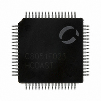
C8051F023R Silicon Laboratories Inc, C8051F023R Datasheet - Page 237

C8051F023R
Manufacturer Part Number
C8051F023R
Description
IC 8051 MCU 64K FLASH 64TQFP
Manufacturer
Silicon Laboratories Inc
Series
C8051F02xr
Specifications of C8051F023R
Core Processor
8051
Core Size
8-Bit
Speed
25MHz
Connectivity
EBI/EMI, SMBus (2-Wire/I²C), SPI, UART/USART
Peripherals
Brown-out Detect/Reset, POR, PWM, Temp Sensor, WDT
Number Of I /o
32
Program Memory Size
64KB (64K x 8)
Program Memory Type
FLASH
Ram Size
4.25K x 8
Voltage - Supply (vcc/vdd)
2.7 V ~ 3.6 V
Data Converters
A/D 8x8b, 8x10b; D/A 2x12b
Oscillator Type
Internal
Operating Temperature
-40°C ~ 85°C
Package / Case
64-TQFP, 64-VQFP
Lead Free Status / RoHS Status
Contains lead / RoHS non-compliant
Eeprom Size
-
Other names
336-1035-2
Available stocks
Company
Part Number
Manufacturer
Quantity
Price
Company:
Part Number:
C8051F023R
Manufacturer:
Silicon Laboratories Inc
Quantity:
10 000
- Current page: 237 of 272
- Download datasheet (2Mb)
22.1.3. Mode 2: Baud Rate Generator
Timer 2 can be used as a baud rate generator for UART0 when UART0 is operated in modes 1 or 3 (refer to Section
“20.1. UART0 Operational
Rate Generator mode, Timer 2 works similarly to the auto-reload mode. On overflow, the 16-bit value held in the two
capture registers (RCAP2H, RCAP2L) is automatically loaded into the counter/timer register. However, the TF2
overflow flag is not set and no interrupt is generated. Instead, the overflow event is used as the input to the UART's
shift clock. Timer 2 overflows can be selected to generate baud rates for transmit and/or receive independently.
The Baud Rate Generator mode is selected by setting RCLK0 (T2CON.5) and/or TCLK0 (T2CON.2) to ‘1’. When
RCLK0 or TCLK0 is set to logic 1, Timer 2 operates in the auto-reload mode regardless of the state of the CP/RL2
bit. Note that in Baud Rate Generator mode, the Timer 2 timebase is the system clock divided by two. When selected
as the UART0 baud clock source, Timer 2 defines the UART0 baud rate as follows:
Baud Rate = SYSCLK / ((65536 - [RCAP2H, RCAP2L] ) * 32)
If a different time base is required, setting the C/T2 bit to logic 1 will allow the timebase to be derived from the exter-
nal input pin T2. In this case, the baud rate for the UART is calculated as:
Baud Rate = F
Where F
held in the capture registers.
As explained above, in Baud Rate Generator mode, Timer 2 does not set the TF2 overflow flag and therefore cannot
generate an interrupt. However, if EXEN2 is set to logic 1, a high-to-low transition on the T2EX input pin will set the
EXF2 flag and a Timer 2 interrupt will occur if enabled. Therefore, the T2EX input may be used as an additional
external interrupt source.
SYSCLK
Overflow
Timer 1
T2EX
CLK
T2
is the frequency of the signal (TCLK) supplied to Timer 2 and [RCAP2H, RCAP2L] is the 16-bit value
CLK
Crossbar
Crossbar
/ ( (65536 - [RCAP2H, RCAP2L] ) * 16)
2
2
EXEN2
TR2
Modes” on page
C/T2
0
1
M
O
S
D
0
0
1
Figure 22.13. T2 Mode 2 Block Diagram
S
S
T
A
T
0
PCON
S
M
O
D
1
S
S
A
T
T
1
O
S
T
P
D
L
E
I
206
TCLK
for more information on the UART0 operational modes). In Baud
CP/RL2
RCAP2L
EXEN2
TCLK0
RCLK0
EXF2
C/T2
TR2
TF2
TL2
Rev. 1.4
RCAP2H
TH2
Interrupt
Reload
Timer 2
Overflow
C8051F020/1/2/3
TCLK0
RCLK0
0
1
0
1
16
16
RX0 Clock
TX0 Clock
237
Related parts for C8051F023R
Image
Part Number
Description
Manufacturer
Datasheet
Request
R
Part Number:
Description:
SMD/C°/SINGLE-ENDED OUTPUT SILICON OSCILLATOR
Manufacturer:
Silicon Laboratories Inc
Part Number:
Description:
Manufacturer:
Silicon Laboratories Inc
Datasheet:
Part Number:
Description:
N/A N/A/SI4010 AES KEYFOB DEMO WITH LCD RX
Manufacturer:
Silicon Laboratories Inc
Datasheet:
Part Number:
Description:
N/A N/A/SI4010 SIMPLIFIED KEY FOB DEMO WITH LED RX
Manufacturer:
Silicon Laboratories Inc
Datasheet:
Part Number:
Description:
N/A/-40 TO 85 OC/EZLINK MODULE; F930/4432 HIGH BAND (REV E/B1)
Manufacturer:
Silicon Laboratories Inc
Part Number:
Description:
EZLink Module; F930/4432 Low Band (rev e/B1)
Manufacturer:
Silicon Laboratories Inc
Part Number:
Description:
I°/4460 10 DBM RADIO TEST CARD 434 MHZ
Manufacturer:
Silicon Laboratories Inc
Part Number:
Description:
I°/4461 14 DBM RADIO TEST CARD 868 MHZ
Manufacturer:
Silicon Laboratories Inc
Part Number:
Description:
I°/4463 20 DBM RFSWITCH RADIO TEST CARD 460 MHZ
Manufacturer:
Silicon Laboratories Inc
Part Number:
Description:
I°/4463 20 DBM RADIO TEST CARD 868 MHZ
Manufacturer:
Silicon Laboratories Inc
Part Number:
Description:
I°/4463 27 DBM RADIO TEST CARD 868 MHZ
Manufacturer:
Silicon Laboratories Inc
Part Number:
Description:
I°/4463 SKYWORKS 30 DBM RADIO TEST CARD 915 MHZ
Manufacturer:
Silicon Laboratories Inc
Part Number:
Description:
N/A N/A/-40 TO 85 OC/4463 RFMD 30 DBM RADIO TEST CARD 915 MHZ
Manufacturer:
Silicon Laboratories Inc
Part Number:
Description:
I°/4463 20 DBM RADIO TEST CARD 169 MHZ
Manufacturer:
Silicon Laboratories Inc


