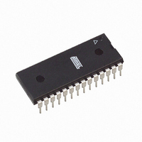
ATMEGA88-20PU Atmel, ATMEGA88-20PU Datasheet - Page 365

ATMEGA88-20PU
Manufacturer Part Number
ATMEGA88-20PU
Description
IC AVR MCU 8K 20MHZ 5V 28DIP
Manufacturer
Atmel
Series
AVR® ATmegar
Specifications of ATMEGA88-20PU
Core Processor
AVR
Core Size
8-Bit
Speed
20MHz
Connectivity
I²C, SPI, UART/USART
Peripherals
Brown-out Detect/Reset, POR, PWM, WDT
Number Of I /o
23
Program Memory Size
8KB (4K x 16)
Program Memory Type
FLASH
Eeprom Size
512 x 8
Ram Size
1K x 8
Voltage - Supply (vcc/vdd)
2.7 V ~ 5.5 V
Data Converters
A/D 6x10b
Oscillator Type
Internal
Operating Temperature
-40°C ~ 85°C
Package / Case
28-DIP (0.300", 7.62mm)
Cpu Family
ATmega
Device Core
AVR
Device Core Size
8b
Frequency (max)
20MHz
Interface Type
SPI/TWI/USART
Total Internal Ram Size
1KB
# I/os (max)
23
Number Of Timers - General Purpose
3
Operating Supply Voltage (typ)
3.3/5V
Operating Supply Voltage (max)
5.5V
Operating Supply Voltage (min)
2.7V
On-chip Adc
6-chx10-bit
Instruction Set Architecture
RISC
Operating Temp Range
-40C to 85C
Operating Temperature Classification
Industrial
Mounting
Through Hole
Pin Count
28
Package Type
PDIP
Processor Series
ATMEGA8x
Core
AVR8
Data Bus Width
8 bit
Data Ram Size
1 KB
Maximum Clock Frequency
20 MHz
Number Of Programmable I/os
23
Number Of Timers
3
Operating Supply Voltage
2.7 V to 5.5 V
Maximum Operating Temperature
+ 85 C
Mounting Style
Through Hole
3rd Party Development Tools
EWAVR, EWAVR-BL
Development Tools By Supplier
ATAVRDRAGON, ATSTK500, ATSTK600, ATAVRISP2, ATAVRONEKIT, ATAVRTS2080A, ATASTK512-EK1-IND
Minimum Operating Temperature
- 40 C
Package
28PDIP
Family Name
ATmega
Maximum Speed
20 MHz
For Use With
ATAVRDRAGON - KIT DRAGON 32KB FLASH MEM AVRATAVRISP2 - PROGRAMMER AVR IN SYSTEM
Lead Free Status / RoHS Status
Lead free / RoHS Compliant
- Current page: 365 of 378
- Download datasheet (8Mb)
35.13 Rev. 2545G-06/06
2545S–AVR–07/10
4.
5.
6.
7.
8.
9.
10.
11.
12.
13.
14.
1.
2.
3.
4.
5.
6.
7.
8.
9.
10.
11.
12.
13.
14.
15.
16.
17
18.
19.
20.
Updated code example in
Added Addresses in Registers.
Updated
Updated
Updated
Updatad
Updated
Updated
Updated
Updated note in
Added rev. C and D in
Updated
Updated
Updated
Updated bit description in
132.
Updated
Table 15-2 on page
3 on page
page
Added Note to
page
Updated
Updated
Updated
Updated
13-3 on page
Updated note for
Updated
Updated
Updated
Updated Features in
Updated
Updated
Added
Updated
Updated rev. A in
286.
299.
Table 28-1 on page
“System Control and Reset” on page
“Brown-out Detection” on page
“Fast PWM Mode” on page
Table 14-3 on page
“Setting the Boot Loader Lock Bits by SPM” on page
“Signature Bytes” on page 287
“Electrical Characteristics” on page
“Errata” on page
“Calibrated Internal RC Oscillator” on page
Table 8-12 on page
“ADC Noise Reduction Mode” on page
“Bit 2 - PRSPI: Power Reduction Serial Peripheral Interface” on page
“TCCR0B – Timer/Counter Control Register B” on page
“Fast PWM Mode” on page
“Asynchronous Operation of Timer/Counter2” on page
“SPI – Serial Peripheral Interface” on page
“UCSRnA – USART MSPIM Control and Status Register n A” on page
“Bit 6 – ACBG: Analog Comparator Bandgap Select” on page
“Prescaling and Conversion Timing” on page
“Limitations of debugWIRE” on page
Figure 15-7 on page
153,
77.
Table 25-1 on page
Table 17-6 on page
“Bit Rate Generator Unit” on page
Table 9-2 on page
“Errata ATmega48” on page
129,
“Analog-to-Digital Converter” on page
“Errata ATmega48” on page
Table 15-3 on page
“SPI – Serial Peripheral Interface” on page
356.
“TCCR1C – Timer/Counter1 Control Register C” on page
305.
34,
100,
121,
Table 9-1 on page
Table 14-6 on page
264,
Figure 29-45 on page
154,
42.
120.
120.
Table 26-5 on page
46.
Table 17-8 on page
302.
130,
260.
44.
356.
39.
Table 15-4 on page
215.
38,
356.
ATmega48/88/168
160.
32.
246.
101,
Table 10-1 on page
338.
243.
Table 14-8 on page
278, and
155, and
276.
150.
103.
160.
Table 27-17 on
131,
Table 27-5 on
241.
Table 17-
53,
43.
Table
205.
102,
365
Related parts for ATMEGA88-20PU
Image
Part Number
Description
Manufacturer
Datasheet
Request
R

Part Number:
Description:
IC MCU AVR 8K 5V 20MHZ 32-TQFP
Manufacturer:
Atmel
Datasheet:

Part Number:
Description:
Manufacturer:
Atmel Corporation
Datasheet:

Part Number:
Description:
Manufacturer:
Atmel Corporation
Datasheet:

Part Number:
Description:
MCU AVR 8K FLASH 15MHZ 32-QFN
Manufacturer:
Atmel
Datasheet:

Part Number:
Description:
IC AVR MCU 8K 20MHZ 5V 32TQFP
Manufacturer:
Atmel
Datasheet:

Part Number:
Description:
IC AVR MCU 8K 20MHZ 5V 32-QFN
Manufacturer:
Atmel
Datasheet:

Part Number:
Description:
IC MCU AVR 8K 5V 20MHZ 32-TQFP
Manufacturer:
Atmel
Datasheet:

Part Number:
Description:
IC MCU AVR 8K 5V 20MHZ 32-QFN
Manufacturer:
Atmel
Datasheet:

Part Number:
Description:
IC MCU AVR 8K 5V 20MHZ 32-QFN
Manufacturer:
Atmel
Datasheet:

Part Number:
Description:
IC MCU AVR 8K 5V 20MHZ 28-DIP
Manufacturer:
Atmel
Datasheet:

Part Number:
Description:
IC MCU AVR 8K 5V 20MHZ 28-DIP
Manufacturer:
Atmel
Datasheet:

Part Number:
Description:
MCU AVR 8K FLASH 20MHZ 32TQFP
Manufacturer:
Atmel
Datasheet:

Part Number:
Description:
MCU AVR 8K FLASH 20MHZ 32QFN
Manufacturer:
Atmel
Datasheet:


