AT91FR40162SB-CU Atmel, AT91FR40162SB-CU Datasheet
AT91FR40162SB-CU
Specifications of AT91FR40162SB-CU
Available stocks


Related parts for AT91FR40162SB-CU


AT91FR40162SB-CU Summary of contents
Page 1
... C to 85° C Temperature Range • Available in a 121-ball 1.26 mm BGA Package with 0.8 mm Ball Pitch ® ® Thumb Processor Core AT91 ARM Thumb-based Microcontrollers AT91FR40162SB Preliminary Summary NOTE: This is a summary document. The complete document is available on the Atmel website at www.atmel.com. 6410BS–ATARM–12-Jan-10 ...
Page 2
... The AT91FR40162SB is pin-to-pin compatible to the AT91FR40162S, so the AT91FR40162SB can be soldered in place of the AT91FR40162S without any other hardware changes. The AT91FR40162SB does not feature a VPP pin, thus ball D5 of the 121-ball BGA package of the AT91FR40162SB is NC (Not connected). This ball can either be connected to a supply up to 13V (as could be the VPP ball of the AT91FR40162S), grounded or left unconnected ...
Page 3
... Users who managed the programming of the flash with the CFI algorithm on the AT91FR40162S should adapt their programming for the AT91FR40162SB. 2.3.5 Fully Green Package The AT91FR40162S is RoHS compliant, whereas the AT91FR40162SB is fully Green qualified. This has no impact on the soldering profile to be used, but only improves environmental considerations. 6410BS–ATARM–12-Jan-10 AT91FR40162SB (Table 12-5, “ ...
Page 4
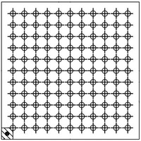
... Pin Configuration Figure 3-1. AT91FR40162SB Pinout for 121-ball BGA Package (Top View) A1 Corner 1 2 P21/TXD1 P19 NTRI P22 P20 RXD1 SCK1 VDDIO GND P23 MCKI P24 P25 NWDOVF BMS MCK0 GND TMS NWE TDO NWR0 P26 VDDCORE VDDIO NCS2 NWAIT GND ...
Page 5
... Signal Description Table 4-1. AT91FR40162SB Signal Description Module Name Function A0 - A23 Address Bus D0 - D15 Data Bus NCS0 - NCS3 External Chip Select CS4 - CS7 External Chip Select NWR0 Lower Byte 0 Write Signal NWR1 Upper Byte 1 Write Signal NRD Read Signal EBI NWE ...
Page 6
... Table 4-1. AT91FR40162SB Signal Description (Continued) Module Name Function NCSF Flash Memory Select Flash NBUSY Flash Memory Busy Output Memory NRSTF Flash Memory Reset Input VDDIO Power Power VDDCORE Power GND Ground AT91FR40162SB 6 Active Type Level Comments Input Low Enables Flash Memory when pulled low ...
Page 7
... Block Diagram Figure 5-1. 6410BS–ATARM–12-Jan-10 AT91FR40162SB Block Diagram Interface Bus External EBI: AT91FR40162SB 7 ...
Page 8
... Memories The AT91FR40162SB embeds 256K bytes of internal SRAM. The internal memory is directly connected to the 32-bit data bus and is single-cycle accessible. This provides maximum perfor- mance of 67 MIPS at 75 MHz by using the ARM instruction set of the processor, minimizing system power consumption and improving on the performance of separate memory solutions ...
Page 9
... Peripheral Data Controller (PDC) channels. The 3-channel, 16-bit Timer Counter (TC) is highly programmable and supports capture or waveform modes. Each TC channel can be programmed to measure or generate different kinds of waves, and can detect and control two input/output signals. The TC has also 3 external clock signals. 6410BS–ATARM–12-Jan-10 AT91FR40162SB 9 ...
Page 10
... Master Clock The AT91FR40162SB has a fully static design and works on the Master Clock (MCK), provided on the MCKI pin from an external source. The Master Clock is also provided as an output of the device on the pin MCKO, which is multi- plexed with a general purpose I/O line ...
Page 11
... Tri-state Mode The AT91FR40162SB microcontroller provides a tri-state mode, which is used for debug pur- poses. This enables the connection of an emulator probe to an application board without having to desolder the device from the target board. In tri-state mode, all the output pin drivers of the AT91R40008 microcontroller are disabled ...
Page 12
... In any of these address spaces, the ARM7TDMI operates in little-endian mode only. 7.6.1 Internal Memories The AT91FR40162SB microcontroller integrates 256K bytes of internal SRAM bits wide and single-clock cycle accessible. Byte (8-bit), half-word (16-bit) and word (32-bit) accesses are supported and are executed within one cycle. Fetching either Thumb or ARM instructions is sup- ported, and internal memory can store two times as many Thumb instructions as ARM instructions ...
Page 13
... AT91FR40162SB uses a remap command that enables switching between the boot memory and the internal primary SRAM bank addresses. The remap command is accessible through the EBI User Interface by writing one in RCB of EBI_RCR (Remap Control Register). Performing a remap command is mandatory if access to the other external devices (connected to chip selects required ...
Page 14
... Program Inhibit – holding any one of OE low, CE high or WE high inhibits program cycles. • Noise Filter – pulses of less than a certain duration on the inputs will not initiate a program cycle. AT91FR40162SB 14 6410BS–ATARM–12-Jan-10 ...
Page 15
... Flash Memory Uploader Operations The Flash Memory Uplo ader requires the encapsulated Flash to be used as the AT91FR40162SB boot memory and a valid clock to be applied to MCKI. After reset, the Flash Memory Uploader immediately recopies itself into the internal SRAM and jumps to it. The follow- ing operation requires this memory resource only ...
Page 16
... Note that in the event that the Flash Memory Uploader is erased from the first sector while the new final application is not yet programmed, and while the target system power supply is switched off, it leads to a non-recoverable error and the AT91FR40162SB cannot be re-pro- grammed by using the Flash Memory Uploader. ...
Page 17
... Peripheral Data Controller The AT91FR40162SB has a 4-channel PDC dedicated to the two on-chip USARTs. One PDC channel is dedicated to the receiver and one to the transmitter of each USART. The user interface of a PDC channel is integrated in the memory space of each USART. It con- tains a 32-bit Address Pointer Register (RPR or TPR) and a 16-bit Transfer Counter Register (RCR or TCR) ...
Page 18
... PIO: Parallel I/O Controller The AT91FR40162SB has 32 programmable I/O lines. Six pins are dedicated as general-pur- pose I/O pins. Other I/O lines are multiplexed with an external signal of a peripheral to optimize the use of available package pins. The PIO controller enables generation of an interrupt on input change and insertion of a simple input glitch filter on any of the PIO pins ...
Page 19
... TC: Timer Counter The AT91FR40162SB features a Timer Counter block that includes three identical 16-bit timer counter channels. Each channel can be independently programmed to perform a wide range of functions including frequency measurement, event counting, interval measurement, pulse gen- eration, delay timing and pulse width modulation. ...
Page 20
... Ordering Information Table 9-1. Ordering Information Ordering Code AT91FR40162SB-CU AT91FR40162SB 20 Package Package Type BGA 121 Green Temperature Operating Range Industrial (-40° 85° C) 6410BS–ATARM–12-Jan-10 ...
Page 21
... Revision History Doc. Rev Comments 6410AS First issue 6410BS Section 2.3.3 “Erase Cycle 6410BS–ATARM–12-Jan-10 Timings”, updated section. AT91FR40162SB Change Request Ref. 5617 21 ...
Page 22
... Disclaimer: The information in this document is provided in connection with Atmel products. No license, express or implied, by estoppel or otherwise, to any intellectual property right is granted by this document or in connection with the sale of Atmel products. EXCEPT AS SET FORTH IN ATMEL’S TERMS AND CONDI- TIONS OF SALE LOCATED ON ATMEL’S WEB SITE, ATMEL ASSUMES NO LIABILITY WHATSOEVER AND DISCLAIMS ANY EXPRESS, IMPLIED OR STATUTORY WARRANTY RELATING TO ITS PRODUCTS INCLUDING, BUT NOT LIMITED TO, THE IMPLIED WARRANTY OF MERCHANTABILITY, FITNESS FOR A PARTICULAR PURPOSE, OR NON-INFRINGEMENT ...