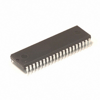
MC68HC705C8ACP Freescale Semiconductor, MC68HC705C8ACP Datasheet - Page 111

MC68HC705C8ACP
Manufacturer Part Number
MC68HC705C8ACP
Description
IC MCU 4MHZ 8K OTP 40-DIP
Manufacturer
Freescale Semiconductor
Series
HC05r
Datasheet
1.MC68HC705C8ACFN.pdf
(222 pages)
Specifications of MC68HC705C8ACP
Core Processor
HC05
Core Size
8-Bit
Speed
2.1MHz
Connectivity
SCI, SPI
Peripherals
POR, WDT
Number Of I /o
24
Program Memory Size
8KB (8K x 8)
Program Memory Type
OTP
Ram Size
304 x 8
Voltage - Supply (vcc/vdd)
3 V ~ 5.5 V
Oscillator Type
Internal
Operating Temperature
-40°C ~ 85°C
Package / Case
40-DIP (0.600", 15.24mm)
Lead Free Status / RoHS Status
Contains lead / RoHS non-compliant
Eeprom Size
-
Data Converters
-
Available stocks
Company
Part Number
Manufacturer
Quantity
Price
Company:
Part Number:
MC68HC705C8ACP
Manufacturer:
MOTOROLA
Quantity:
13
Company:
Part Number:
MC68HC705C8ACPE
Manufacturer:
ON
Quantity:
1 000
- Current page: 111 of 222
- Download datasheet (3Mb)
9.4 PROM Programming Routines
9.4.1 Program and Verify PROM
MC68HC705C8A — Rev. 3
MOTOROLA
This subsection describes the routines necessary to program, verify, and
secure the PROM device, and other routines available to the user.
The program and verify PROM routine copies the contents of the
external EPROM into the MCU PROM with direct correspondence
between the addresses. Memory addresses in the MCU that are not
implemented in PROM are skipped. Unprogrammed addresses in the
EPROM being copied should contain $00 bytes to speed up the
programming process.
To run the program and verify the PROM routine on the PROM MCU,
take these steps:
At this point, if no other MCU is to be programmed or secured, remove
V
MCU being programmed, the user can then set switches S3, S4, S5, and
S6 to the positions necessary to select the next routine, and begin the
routine by setting switch 2 to the OUT position. If no other routine is to
be performed, remove V
the programming socket.
PP
1. Set switch 1 in the ON position (restores V
2. Restore the V
3. Set switches S3, S4, S5, and S6 in the OFF position (selects
4. Set switch 2 in the OUT position (routine is activated).
5. Set switch 2 in the RESET position.
Freescale Semiconductor, Inc.
power from the board. If another routine is to be performed on the
For More Information On This Product,
proper routine).
The red light-emitting diode (LED) is illuminated, showing that the
programming part of the routine is running. The LED goes out
when programming is finished. The verification part of the routine
now begins. When the green LED is illuminated, verification is
successfully completed and the routine is finished.
EPROM/OTPROM (PROM)
Go to: www.freescale.com
PP
power source.
DD
from the board and remove the MCU from
PROM Programming Routines
EPROM/OTPROM (PROM)
DD
).
Technical Data
111
Related parts for MC68HC705C8ACP
Image
Part Number
Description
Manufacturer
Datasheet
Request
R
Part Number:
Description:
Manufacturer:
Freescale Semiconductor, Inc
Datasheet:
Part Number:
Description:
Manufacturer:
Freescale Semiconductor, Inc
Datasheet:
Part Number:
Description:
Manufacturer:
Freescale Semiconductor, Inc
Datasheet:
Part Number:
Description:
Manufacturer:
Freescale Semiconductor, Inc
Datasheet:
Part Number:
Description:
Manufacturer:
Freescale Semiconductor, Inc
Datasheet:
Part Number:
Description:
Manufacturer:
Freescale Semiconductor, Inc
Datasheet:
Part Number:
Description:
Manufacturer:
Freescale Semiconductor, Inc
Datasheet:
Part Number:
Description:
Manufacturer:
Freescale Semiconductor, Inc
Datasheet:
Part Number:
Description:
Manufacturer:
Freescale Semiconductor, Inc
Datasheet:
Part Number:
Description:
Manufacturer:
Freescale Semiconductor, Inc
Datasheet:
Part Number:
Description:
Manufacturer:
Freescale Semiconductor, Inc
Datasheet:
Part Number:
Description:
Manufacturer:
Freescale Semiconductor, Inc
Datasheet:
Part Number:
Description:
Manufacturer:
Freescale Semiconductor, Inc
Datasheet:
Part Number:
Description:
Manufacturer:
Freescale Semiconductor, Inc
Datasheet:
Part Number:
Description:
Manufacturer:
Freescale Semiconductor, Inc
Datasheet:


