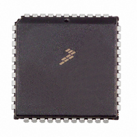
MC68HC705C9ACFN Freescale Semiconductor, MC68HC705C9ACFN Datasheet - Page 52

MC68HC705C9ACFN
Manufacturer Part Number
MC68HC705C9ACFN
Description
IC MCU 2.1MHZ 16K OTP 44-PLCC
Manufacturer
Freescale Semiconductor
Series
HC05r
Datasheet
1.MC705C9ACPE.pdf
(118 pages)
Specifications of MC68HC705C9ACFN
Core Processor
HC05
Core Size
8-Bit
Speed
2.1MHz
Connectivity
SCI, SPI
Peripherals
POR, WDT
Number Of I /o
24
Program Memory Size
16KB (16K x 8)
Program Memory Type
OTP
Ram Size
352 x 8
Voltage - Supply (vcc/vdd)
3 V ~ 5.5 V
Oscillator Type
Internal
Operating Temperature
-40°C ~ 85°C
Package / Case
44-PLCC
Lead Free Status / RoHS Status
Contains lead / RoHS non-compliant
Eeprom Size
-
Data Converters
-
Available stocks
Company
Part Number
Manufacturer
Quantity
Price
Company:
Part Number:
MC68HC705C9ACFN
Manufacturer:
Freescale Semiconductor
Quantity:
10 000
Company:
Part Number:
MC68HC705C9ACFNE
Manufacturer:
RFMD
Quantity:
8 729
Company:
Part Number:
MC68HC705C9ACFNE
Manufacturer:
Freescale Semiconductor
Quantity:
10 000
Capture/Compare Timer
8.2 Timer Operation
The core of the capture/compare timer is a 16-bit free-running counter. The counter provides the timing
reference for the input capture and output compare functions. The input capture and output compare
functions provide a means to latch the times at which external events occur, to measure input waveforms,
and to generate output waveforms and timing delays. Software can read the value in the 16-bit
free-running counter at any time without affecting the counter sequence.
Because of the 16-bit timer architecture, the I/O registers for the input capture and output compare
functions are pairs of 8-bit registers.
Because the counter is 16 bits long and preceded by a fixed divide-by-4 prescaler, the counter rolls over
every 262,144 internal clock cycles. Timer resolution with a 4-MHz crystal is 2 µs.
8.2.1 Input Capture
The input capture function is a means to record the time at which an external event occurs. When the
input capture circuitry detects an active edge on the TCAP pin, it latches the contents of the timer registers
into the input capture registers. The polarity of the active edge is programmable.
Latching values into the input capture registers at successive edges of the same polarity measures the
period of the input signal on the TCAP pin. Latching values into the input capture registers at successive
edges of opposite polarity measures the pulse width of the signal.
8.2.2 Output Compare
The output compare function is a means of generating an output signal when the 16-bit counter reaches
a selected value. Software writes the selected value into the output compare registers. On every fourth
internal clock cycle the output compare circuitry compares the value of the counter to the value written in
the output compare registers. When a match occurs, the timer transfers the programmable output level
bit (OLVL) from the timer control register to the TCMP pin.
The programmer can use the output compare register to measure time periods, to generate timing delays,
or to generate a pulse of specific duration or a pulse train of specific frequency and duty cycle on the
TCMP pin.
8.3 Timer I/O Registers
The following I/O registers control and monitor timer operation:
52
•
•
•
•
•
•
Timer control register (TCR)
Timer status register (TSR)
Timer registers (TRH and TRL)
Alternate timer registers (ATRH and ATRL)
Input capture registers (ICRH and ICRL)
Output compare registers (OCRH and OCRL)
MC68HC05C9A Advance Information Data Sheet, Rev. 4.1
Freescale Semiconductor


