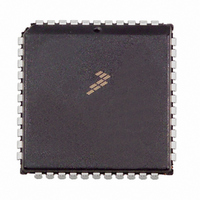
MC68HC705C9ACFN Freescale Semiconductor, MC68HC705C9ACFN Datasheet - Page 64

MC68HC705C9ACFN
Manufacturer Part Number
MC68HC705C9ACFN
Description
IC MCU 2.1MHZ 16K OTP 44-PLCC
Manufacturer
Freescale Semiconductor
Series
HC05r
Datasheet
1.MC705C9ACPE.pdf
(118 pages)
Specifications of MC68HC705C9ACFN
Core Processor
HC05
Core Size
8-Bit
Speed
2.1MHz
Connectivity
SCI, SPI
Peripherals
POR, WDT
Number Of I /o
24
Program Memory Size
16KB (16K x 8)
Program Memory Type
OTP
Ram Size
352 x 8
Voltage - Supply (vcc/vdd)
3 V ~ 5.5 V
Oscillator Type
Internal
Operating Temperature
-40°C ~ 85°C
Package / Case
44-PLCC
Lead Free Status / RoHS Status
Contains lead / RoHS non-compliant
Eeprom Size
-
Data Converters
-
Available stocks
Company
Part Number
Manufacturer
Quantity
Price
Company:
Part Number:
MC68HC705C9ACFN
Manufacturer:
Freescale Semiconductor
Quantity:
10 000
Company:
Part Number:
MC68HC705C9ACFNE
Manufacturer:
RFMD
Quantity:
8 729
Company:
Part Number:
MC68HC705C9ACFNE
Manufacturer:
Freescale Semiconductor
Quantity:
10 000
Serial Communications Interface (SCI)
9.11 Start Bit Detection
When the input (idle) line is detected low, it is tested for three more sample times (referred to as the start
edge verification samples in
0, a valid start bit has been detected; otherwise, the line is assumed to be idle. A noise flag is set if all
three verification samples do not detect a logic 0. Thus, a valid start bit could be assumed with a set noise
flag present.
If a framing error has occurred without detection of a break (10 0s for
8-bit format or 11 0s for 9-bit format), the circuit continues to operate as if there actually was a stop bit,
and the start edge will be placed artificially. The last bit received in the data shift register is inverted to a
logic 1, and the three logic 1 start qualifiers (shown in
during the interval when detection of a start bit is anticipated (see
be accepted no sooner than it is anticipated.
If the receiver detects that a break (RDRF = 1, FE = 1, receiver data register = $003B) produced the
framing error, the start bit will not be artificially induced and the receiver must actually detect a logic 1
before the start bit can be recognized (see
64
EXPECTED STOP
RDI
BREAK
Figure 9-6. SCI Artificial Start Following a Frame Error
RDI
RDI
DATA
DATA
MC68HC05C9A Advance Information Data Sheet, Rev. 4.1
Figure
Figure 9-7. SCI Start Bit Following a Break
b) Case 2: Receive line high during expected start edge
a) Case 1: Receive line low during artificial edge
DATA SAMPLES
DATA SAMPLES
DATA SAMPLES
EXPECTED STOP
9-4). If at least two of these three verification samples detect a logic
EXPECTED STOP
Figure
9-7).
Figure
QUALIFIERS
START EDGE
ARTIFICIAL EDGE
START
9-4) are forced into the sample shift register
START BIT
VERIFICATION
Figure
START EDGE
START BIT
SAMPLES
DETECTED AS VALID START EDGE
START BIT
9-6); therefore, the start bit will
DATA
DATA
Freescale Semiconductor


