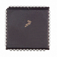
MC68HC711D3CFNE2 Freescale Semiconductor, MC68HC711D3CFNE2 Datasheet - Page 48

MC68HC711D3CFNE2
Manufacturer Part Number
MC68HC711D3CFNE2
Description
IC MCU 8BIT 3MHZ 44-PLCC
Manufacturer
Freescale Semiconductor
Series
HC11r
Specifications of MC68HC711D3CFNE2
Core Processor
HC11
Core Size
8-Bit
Speed
2MHz
Connectivity
SCI, SPI
Peripherals
POR, WDT
Number Of I /o
26
Program Memory Size
4KB (4K x 8)
Program Memory Type
OTP
Ram Size
192 x 8
Voltage - Supply (vcc/vdd)
4.5 V ~ 5.5 V
Oscillator Type
Internal
Operating Temperature
-40°C ~ 85°C
Package / Case
44-PLCC
Lead Free Status / RoHS Status
Lead free / RoHS Compliant
Eeprom Size
-
Data Converters
-
Available stocks
Company
Part Number
Manufacturer
Quantity
Price
Company:
Part Number:
MC68HC711D3CFNE2
Manufacturer:
ALLEGEO
Quantity:
4 492
Company:
Part Number:
MC68HC711D3CFNE2
Manufacturer:
Freescale Semiconductor
Quantity:
10 000
CONFIG — Configuration Control Register
5.1.6 CONFIG Register
Bits [7:4] and 0 — Not implemented
NOCOP — COP System Disable
ROMON — Enable On-Chip ROM
5.2 Effects of Reset
5.2.1 CPU
5.2.2 Memory Map
5-4
POR or RESET Pin
Clock Monitor Failure
COP Watchdog Time-out
RESET:
Always read zero
This bit is cleared out of reset in normal modes, enabling the COP system. It is set out
of reset in special modes. NOCOP is writable once in normal modes and at any time
in special modes.
Refer to SECTION 4 OPERATING MODES AND ON-CHIP MEMORY.
When a reset condition is recognized, the internal registers and control bits are forced
to an initial state. Depending on the cause of the reset and the operating mode, the
reset vector can be fetched from any of six possible locations. Refer to Table 5-2.
These initial states then control on-chip peripheral systems to force them to known
startup states, as follows:
After reset, the CPU fetches the restart vector from the appropriate address during the
first three cycles, and begins executing instructions. The stack pointer and other CPU
registers are indeterminate immediately after reset; however, the X and I interrupt
mask bits in the condition code register (CCR) are set to mask any interrupt requests.
Also, the S bit in the CCR is set to inhibit the STOP mode.
After reset, the INIT register is initialized to $00, putting the 192 bytes of RAM at loca-
tions $0040 through $00FF, and the control registers at locations $0000 through
$003F.
0 = The COP system is enabled as the MCU comes out of reset.
1 = The COP system is disabled and does not generate system resets.
Cause of Reset
Bit 7
Table 5-2 Reset Cause, Reset Vector, and Operating Mode
0
0
Freescale Semiconductor, Inc.
6
0
0
For More Information On This Product,
RESETS AND INTERRUPTS
Go to: www.freescale.com
5
0
0
Normal Mode Vector
$FFFC, FFFD
$FFFA, FFFB
$FFFE, FFFF
4
0
0
3
0
0
NOCOP
—
2
Special Test or Bootstrap
$BFFC, $BFFD
$BFFA, BFFB
$BFFE, BFFF
ROMON
TECHNICAL DATA
—
1
$003F
Bit 0
0
0


