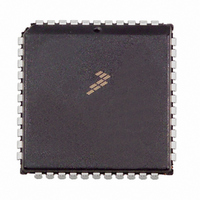
MC68HC711D3CFNE2 Freescale Semiconductor, MC68HC711D3CFNE2 Datasheet - Page 77

MC68HC711D3CFNE2
Manufacturer Part Number
MC68HC711D3CFNE2
Description
IC MCU 8BIT 3MHZ 44-PLCC
Manufacturer
Freescale Semiconductor
Series
HC11r
Specifications of MC68HC711D3CFNE2
Core Processor
HC11
Core Size
8-Bit
Speed
2MHz
Connectivity
SCI, SPI
Peripherals
POR, WDT
Number Of I /o
26
Program Memory Size
4KB (4K x 8)
Program Memory Type
OTP
Ram Size
192 x 8
Voltage - Supply (vcc/vdd)
4.5 V ~ 5.5 V
Oscillator Type
Internal
Operating Temperature
-40°C ~ 85°C
Package / Case
44-PLCC
Lead Free Status / RoHS Status
Lead free / RoHS Compliant
Eeprom Size
-
Data Converters
-
Available stocks
Company
Part Number
Manufacturer
Quantity
Price
Company:
Part Number:
MC68HC711D3CFNE2
Manufacturer:
ALLEGEO
Quantity:
4 492
Company:
Part Number:
MC68HC711D3CFNE2
Manufacturer:
Freescale Semiconductor
Quantity:
10 000
Freescale Semiconductor, Inc.
TDRE and TC flags are normally set when the transmitter is first enabled (TE set to
one). The TDRE flag indicates there is room in the transmit queue to store another
data character in the TDR. The TIE bit is the local interrupt mask for TDRE. When TIE
is zero, TDRE must be polled. When TIE and TDRE are one, an interrupt is requested.
The TC flag indicates the transmitter has completed the queue. The TCIE bit is the lo-
cal interrupt mask for TC. When TCIE is zero, TC must be polled; when TCIE is one
and TC is one, an interrupt is requested.
Writing a zero to TE requests that the transmitter stop when it can. The transmitter
completes any transmission in progress before actually shutting down. Only an MCU
reset can cause the transmitter to stop and shut down immediately. If TE is written to
zero when the transmitter is already idle, the pin reverts to its general-purpose I/O
function (synchronized to the bit-rate clock). If anything is being transmitted when TE
is written to zero, that character is completed before the pin reverts to general-purpose
I/O, but any other characters waiting in the transmit queue are lost. The TC and TDRE
flags are set at the completion of this last character, even though TE has been dis-
abled.
The SCI receiver has five status flags, three of which can generate interrupt requests.
The status flags are set by the SCI logic in response to specific conditions in the re-
ceiver. These flags can be read (polled) at any time by software. Refer to Figure 7-4,
which shows SCI interrupt arbitration.
When an overrun takes place, the new character is lost, and the character that was in
its way in the parallel RDR is undisturbed. RDRF is set when a character has been
received and transferred into the parallel RDR. The OR flag is set instead of RDRF if
overrun occurs. A new character is ready to be transferred into RDR before a previous
character is read from RDR.
The NF and FE flags provide additional information about the character in the RDR,
but do not generate interrupt requests.
The last receiver status flag and interrupt source come from the IDLE flag. The RxD
line is idle if it has constantly been at logic one for a full character time. The IDLE flag
is set only after the RxD line has been busy and becomes idle, which prevents repeat-
ed interrupts for the whole time RxD remains idle.
SERIAL COMMUNICATIONS INTERFACE
TECHNICAL DATA
7-11
For More Information On This Product,
Go to: www.freescale.com


