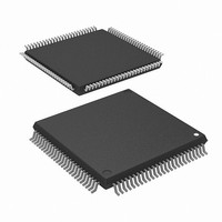
M30626FJPGP#D5C Renesas Electronics America, M30626FJPGP#D5C Datasheet - Page 271

M30626FJPGP#D5C
Manufacturer Part Number
M30626FJPGP#D5C
Description
MCU 3/5V 512K 100-LQFP
Manufacturer
Renesas Electronics America
Series
M16C™ M16C/60r
Datasheet
1.M30622SAFPU5.pdf
(308 pages)
Specifications of M30626FJPGP#D5C
Core Processor
M16C/60
Core Size
16-Bit
Speed
24MHz
Connectivity
I²C, IEBus, UART/USART
Peripherals
DMA, WDT
Number Of I /o
85
Program Memory Size
512KB (512K x 8)
Program Memory Type
FLASH
Ram Size
31K x 8
Voltage - Supply (vcc/vdd)
2.7 V ~ 5.5 V
Data Converters
A/D 26x10b; D/A 2x8b
Oscillator Type
Internal
Operating Temperature
-20°C ~ 85°C
Package / Case
100-LQFP
Lead Free Status / RoHS Status
Contains lead / RoHS non-compliant
Eeprom Size
-
Available stocks
Company
Part Number
Manufacturer
Quantity
Price
- Current page: 271 of 308
- Download datasheet (2Mb)
Chapter 5
5.2.4 Rewrite the Interrupt Control Register
(1) The interrupt control register for any interrupt should be modified in places where no requests for that
(2) To rewrite the interrupt control register for any interrupt after disabling that interrupt, be careful with the
(3) When using the I flag to disable an interrupt, refer to the sample program fragments shown below as
Examples 1 through 3 show how to prevent the I flag from being set to “1” (interrupts enabled) before the
interrupt control register is rewrited, owing to the effects of the internal bus and the instruction queue
buffer.
Changing any bit other than the IR bit
Changing the IR bit
Example 1:Using the NOP instruction to keep the program waiting until
Example 2:Using the dummy read to keep the FSET instruction waiting
Example 3:Using the POPC instruction to changing the I flag
If while executing an instruction, a request for an interrupt controlled by the register being modified
occurs, the IR bit in the register may not be set to “1” (interrupt requested), with the result that the
interrupt request is ignored. If such a situation presents a problem, use the instructions shown below
to modify the register.
Usable instructions: AND, OR, BCLR, BSET
Depending on the instruction used, the IR bit may not always be cleared to “0” (interrupt not re-
quested). Therefore, be sure to use the MOV instruction to clear the IR bit.
interrupt may occur. Otherwise, disable the interrupt before rewriting the interrupt control register.
instruction to be used.
you set the I flag. (Refer to (2) for details about rewrite the interrupt control registers in the sample
program fragments.)
INT_SWITCH1:
INT_SWITCH2:
INT_SWITCH3:
FCLR
AND.B
NOP
NOP
FSET
FCLR
AND.B
MOV.W
FSET
PUSHC
FCLR
AND.B
POPC
Interrupt
the interrupt control register is modified
I
#00h, 0055h
I
I
#00h, 0055h
MEM, R0
I
FLG
I
#00h, 0055h
FLG
; Disable interrupts.
; Set the TA0IC register to “00
; Four NOP instructions are required when using HOLD function.
; Refer to hardware manual about the number of NOP
; instruction
; Enable interrupts.
; Disable interrupts.
; Set the TA0IC register to “00
; Dummy read.
; Enable interrupts.
; Disable interrupts.
; Set the TA0IC register to “00
; Enable interrupts.
253
16
”.
16
16
”.
”.
5.2 Interrupt Control
Related parts for M30626FJPGP#D5C
Image
Part Number
Description
Manufacturer
Datasheet
Request
R

Part Number:
Description:
KIT STARTER FOR M16C/29
Manufacturer:
Renesas Electronics America
Datasheet:

Part Number:
Description:
KIT STARTER FOR R8C/2D
Manufacturer:
Renesas Electronics America
Datasheet:

Part Number:
Description:
R0K33062P STARTER KIT
Manufacturer:
Renesas Electronics America
Datasheet:

Part Number:
Description:
KIT STARTER FOR R8C/23 E8A
Manufacturer:
Renesas Electronics America
Datasheet:

Part Number:
Description:
KIT STARTER FOR R8C/25
Manufacturer:
Renesas Electronics America
Datasheet:

Part Number:
Description:
KIT STARTER H8S2456 SHARPE DSPLY
Manufacturer:
Renesas Electronics America
Datasheet:

Part Number:
Description:
KIT STARTER FOR R8C38C
Manufacturer:
Renesas Electronics America
Datasheet:

Part Number:
Description:
KIT STARTER FOR R8C35C
Manufacturer:
Renesas Electronics America
Datasheet:

Part Number:
Description:
KIT STARTER FOR R8CL3AC+LCD APPS
Manufacturer:
Renesas Electronics America
Datasheet:

Part Number:
Description:
KIT STARTER FOR RX610
Manufacturer:
Renesas Electronics America
Datasheet:

Part Number:
Description:
KIT STARTER FOR R32C/118
Manufacturer:
Renesas Electronics America
Datasheet:

Part Number:
Description:
KIT DEV RSK-R8C/26-29
Manufacturer:
Renesas Electronics America
Datasheet:

Part Number:
Description:
KIT STARTER FOR SH7124
Manufacturer:
Renesas Electronics America
Datasheet:

Part Number:
Description:
KIT STARTER FOR H8SX/1622
Manufacturer:
Renesas Electronics America
Datasheet:

Part Number:
Description:
KIT DEV FOR SH7203
Manufacturer:
Renesas Electronics America
Datasheet:


