LT1464ACS8#PBF Linear Technology, LT1464ACS8#PBF Datasheet
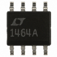
IC OP-AMP JFET INPUT DUAL 8-SOIC

LT1464ACS8#PBF

Manufacturer Part Number
LT1464ACS8#PBF
Description
IC OP-AMP JFET INPUT DUAL 8-SOIC
Manufacturer
Linear Technology
Series
C-Load™r
Type
General Purpose Amplifierr
Datasheet

Specifications of LT1464ACS8#PBF

Amplifier Type
J-FET
Number Of Circuits
2
Slew Rate
0.9 V/µs
Gain Bandwidth Product
1MHz
Current - Input Bias
0.5pA
Voltage - Input Offset
600µV
Current - Supply
145µA
Voltage - Supply, Single/dual (±)
±5 V ~ 15 V
Operating Temperature
0°C ~ 70°C
Mounting Type
Surface Mount
Package / Case
8-SOIC (3.9mm Width)
Rail/rail I/o Type
No
Number Of Elements
2
Unity Gain Bandwidth Product
1MHz
Common Mode Rejection Ratio
76dB
Input Offset Voltage
800uV
Input Bias Current
2pA
Single Supply Voltage (typ)
Not RequiredV
Dual Supply Voltage (typ)
±9/±12/±15/±18V
Voltage Gain In Db
107.96dB
Power Supply Rejection Ratio
81dB
Power Supply Requirement
Dual
Shut Down Feature
No
Single Supply Voltage (min)
Not RequiredV
Single Supply Voltage (max)
Not RequiredV
Dual Supply Voltage (min)
±5V
Dual Supply Voltage (max)
±20V
Technology
BiFET
Operating Temp Range
0C to 70C
Operating Temperature Classification
Commercial
Mounting
Surface Mount
Pin Count
8
Package Type
SOIC N
Lead Free Status / RoHS Status
Lead free / RoHS Compliant
Output Type
-
Current - Output / Channel
-
-3db Bandwidth
-
Lead Free Status / Rohs Status
Compliant

Available stocks

Company
Part Number
Manufacturer
Quantity
Price
Company:
Part Number:
LT1464ACS8#PBFLT1464ACS8
Manufacturer:
LINEAR/凌特
Quantity:
20 000
Company:
Part Number:
LT1464ACS8#PBF
Manufacturer:
LINEAR/凌特
Quantity:
20 000
APPLICATIONS
IN
FEATURES
A
TYPICAL
B
Battery-Powered Systems
Photocurrent Amplifiers
Low Frequency, Micropower Active Filters
Low Droop Track-and-Hold Circuits
Input Bias Current:
Supply Current per Amplifier: 200 A Max
Gain Bandwidth Product: 1MHz Typ
Slew Rate: 0.9V/ s Typ
Input Common Mode Range Includes Positive Rail
Unity-Gain Stable for C-Load
Open-Loop Gain: 1 Million Typ
Guaranteed Specs with 5V, 15V Supplies
Guaranteed Matching Specifications
Standard Pinout: SO-8, SO-14 Package
16
1
2pA Max (LT1464A)
20pA Max (LT1464, LT1465)
1/4 LTC201
1/4 LTC201
Micropower Low Droop Track-and-Hold/Peak Detector
FUNCTION
Track-and-Hold
Positive Peak Detector Reset
Negative Peak Detector Reset
LTC201 switch is open for logic "1".
5
5
6
13
4
APPLICATION
V
V
+
1/2 LT1464
+
15
14
2
3
U
7 R1*
MODE
Track
1
2
1
2
TM
MCT2
MCT2
IN A IN B MODE IN A IN B
6
6
0
0
0
U
Up to 10nF
5
4
5
4
0
0
0
Hold
Store
Store
* R1 = 600
TYPICAL DROOP =
TOTAL SUPPLY CURRENT = 460 A MAX
R1 = 0
2
3
POLYSTYRENE
+
1/2 LT1464
Bias Current JFET Input Op Amps
1
0
1
FOR 5V SUPPLIES
10nF
C1
V
V
FOR 15V SUPPLIES
+
8
4
1
1
0
0.5pA
10nF
1
= 0.05mV/s
1MHz C-Load Picoampere
DESCRIPTION
The LT
micropower op amps (200 A max per amp) to offer
picoampere input bias currents (500fA typ) and unity-gain
stability for capacitive loads up to 10nF. The output can
swing a 10k load to within 1.5V of either supply, just like
op amps that require an order of magnitude more supply
current. This unique combination of performance makes
the LT1464/LT1465 ideal over a wide range of input and
output impedances.
In the design and testing of the LT1464/LT1465, particular
emphasis has been placed on optimizing performance in
the low cost SO-8 (dual) and 14-lead SO (quad) package for
includes the positive rail. Slew rate (0.5V/ s min) and gain
bandwidth product (650kHz min) are 100% tested. A full
set of matching specifications is also provided.
C-Load is a trademark of Linear Technology Corporation.
LT1464 • TA01
15V and 5V supplies. The input common mode range
V
, LTC and LT are registered trademarks of Linear Technology Corporation.
OUT
Dual/Quad Micropower,
®
1464 (dual) and LT1465 (quad) are the first
Small-Signal Response, C
A
V
C
V
S
L
= 1
= 5V, 15V
= 10nF
U
LT1464/LT1465
LOAD
= 10nF
1464 • TA02
1

Related parts for LT1464ACS8#PBF

LT1464ACS8#PBF Summary of contents

Page 1

... The input common mode range includes the positive rail. Slew rate (0.5V/ s min) and gain bandwidth product (650kHz min) are 100% tested. A full set of matching specifications is also provided. , LTC and LT are registered trademarks of Linear Technology Corporation. C-Load is a trademark of Linear Technology Corporation. C1 10nF ...

Page 2

LT1464/LT1465 ABSOLUTE MAXIMUM Supply Voltage ..................................................... 20V Differential Input Voltage ...................................... 40V Input Current ....................................................... 20mA Output Short-Circuit Duration ......................... Indefinite Operating Temperature Range ............... – PACKAGE/ORDER INFORMATION TOP VIEW + ...

Page 3

ELECTRICAL CHARACTERISTICS SYMBOL PARAMETER V Output Voltage Swing OUT SR Slew Rate GBW Gain Bandwidth Product I Supply Current per Amplifier S Channel Separation V Offset Voltage Match (Note Noninverting Bias Current Match B (Note 7) ...

Page 4

LT1464/LT1465 ELECTRICAL CHARACTERISTICS SYMBOL PARAMETER CMRR Common Mode Rejection Match PSRR Power Supply Rejection Match V = 15V 0V, – (Note 2), unless otherwise noted SYMBOL PARAMETER V Input Offset ...

Page 5

W U TYPICAL PERFORMANCE CHARACTERISTICS Input Bias and Offset Current vs Temperature 10000 LT1464/LT1465 LT1464A 1000 100 BIAS CURRENT 10 OFFSET CURRENT 100 50 125 AMBIENT TEMPERATURE ( C) LT1464 • TPC01 Supply Current vs Temperature ...

Page 6

LT1464/LT1465 W U TYPICAL PERFORMANCE CHARACTERISTICS Gain and Phase vs Frequency 15V PHASE 50 PHASE MARGIN = 10pF GAIN 10 0 –10 ...

Page 7

U U APPLICATIONS INFORMATION Phase Reversal Protection Most industry standard JFET input single, dual and quad op amps exhibit phase reversal at the output when the negative common mode limit at the input is exceeded. Common mode range is at ...

Page 8

LT1464/LT1465 U TYPICAL APPLICATIONS R 6.19k 10Hz 4th Order Chebyshev Lowpass Filter (0.01dB Ripple) R1 237k V IN TYPICAL OFFSET 0.6mV 1% TOLERANCES FOR V = 10V IN THE LOW INPUT BIAS CURRENTS ALLOW THE ...

Page 9

PLIFIED SCHE ATIC + – Q15 10 A Q14 R10 Q16 C1 Q28 V EE R16 Q11 ...

Page 10

LT1464/LT1465 PACKAGE DESCRIPTION 0.300 – 0.325 (7.620 – 8.255) 0.009 – 0.015 (0.229 – 0.381) +0.025 0.325 –0.015 +0.635 8.255 –0.381 *THESE DIMENSIONS DO NOT INCLUDE MOLD FLASH OR PROTRUSIONS. MOLD FLASH OR PROTRUSIONS SHALL NOT EXCEED 0.010 INCH (0.254mm) ...

Page 11

... FLASH SHALL NOT EXCEED 0.010" (0.254mm) PER SIDE Information furnished by Linear Technology Corporation is believed to be accurate and reliable. However, no responsibility is assumed for its use. Linear Technology Corporation makes no represen- tation that the interconnection of its circuits as described herein will not infringe on existing patent rights. ...

Page 12

... A Supply Current Per Amplifiers Drives 10 F Capacitive Load, 175kHz GBW R2 10k GAIN TRIM 75k – 1/2 LT1464 OUTPUT + 4 – (R2)( OUT S REF IN * TRW#MTR-5/120ppm LT1464 • TA04 (Max) , 6.3MHz GBW B , 5.3MHz GBW, 1.5pF Input Capacitance n (Max Drift OS 14645fa LT/GP 0197 5K REV A • PRINTED IN USA LINEAR TECHNOLOGY CORPORATION 1996 ...

Related keywords