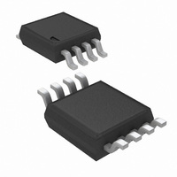
LMV822MMX/NOPB National Semiconductor, LMV822MMX/NOPB Datasheet - Page 13

LMV822MMX/NOPB
Manufacturer Part Number
LMV822MMX/NOPB
Description
IC OP AMP R-R LOW VOLT LP 8-MSOP
Manufacturer
National Semiconductor
Datasheet
1.LMV821M5NOPB.pdf
(24 pages)
Specifications of LMV822MMX/NOPB
Amplifier Type
General Purpose
Number Of Circuits
2
Output Type
Rail-to-Rail
Slew Rate
2 V/µs
Gain Bandwidth Product
5.6MHz
Current - Input Bias
100nA
Voltage - Input Offset
3500µV
Current - Supply
500µA
Current - Output / Channel
45mA
Voltage - Supply, Single/dual (±)
2.5 V ~ 5.5 V, ±1.25 V ~ 2.75 V
Operating Temperature
-40°C ~ 85°C
Mounting Type
Surface Mount
Package / Case
8-MSOP, Micro8™, 8-uMAX, 8-uSOP,
Lead Free Status / RoHS Status
Lead free / RoHS Compliant
-3db Bandwidth
-
Other names
*LMV822MMX
*LMV822MMX/NOPB
LMV822MMX
LMV822MMXTR
*LMV822MMX/NOPB
LMV822MMX
LMV822MMXTR
Available stocks
Company
Part Number
Manufacturer
Quantity
Price
Company:
Part Number:
LMV822MMX/NOPB
Manufacturer:
NSC
Quantity:
19 923
Application Note
3. Dual Amplifier Active Filters (DAAFs)
4. Tri-level Voltage Detector
TELEPHONE-LINE TRANSCEIVER
The telephone-line transceiver of Figure 7 provides a full-
duplexed connection through a PCMCIA, miniature trans-
former. The differential configuration of receiver portion
(UR), cancels reception from the transmitter portion (UT).
Note that the input signals for the differential configuration of
UR, are the transmit voltage (V
R
ance; therefore dividing V
R
chosen to cancel the V
following equation:
Note that Cr is included for canceling out the inadequacies of
the lossy, miniature transformer. Refer to application note
AN-397 for detailed explanation.
“SIMPLE” MIXER (AMPLITUDE MODULATOR)
The mixer of Figure 8 is simple and provides a unique form
of amplitude modulation. Vi is the modulation frequency
(F
carrier frequency (F
inverting and non-inverting unity gain configurations. Offset-
ting a sine wave above ground at Vi results in the oscillo-
scope photo of Figure 9.
The simple mixer can be applied to applications that utilize
the Doppler Effect to measure the velocity of an object. The
difference frequency is one of its output frequency compo-
nents. This difference frequency magnitude (/F
key factor for determining an object’s velocity per the Dop-
pler Effect. If a signal is transmitted to a moving object, the
reflected frequency will be a different frequency. This differ-
ence in transmit and receive frequency is directly propor-
tional to an object’s velocity.
•
•
match
match
FIGURE 7. Telephone-line Transceiver for a PCMCIA
M
), while a +3V square-wave at the gate of Q1, induces a
a. Low-Pass Filter (LPF)
b. High-Pass Filter (HPF)
). The differential configuration of UR has its resistors
is chosen to match the coupled telephone-line imped-
C
). Q1 switches (toggles) U1 between
Modem Card
T
and V
T
(Continued)
by two (assuming R1
T
) and V
T
/2 inputs according to the
T
/2. This is because
M
-F
C
10012833
/) is the
>>
13
DUAL AMPLIFIER ACTIVE FILTERS (DAAFs)
The LMV822/24 bring economy and performance to DAAFs.
The low-pass and the high-pass filters of Figure 10 and
Figure 11 (respectively), offer one key feature: excellent
sensitivity performance. Good sensitivity is when deviations
in component values cause relatively small deviations in a
filter’s parameter such as cutoff frequency (Fc). Single am-
plifier active filters like the Sallen-Key provide relatively poor
sensitivity performance that sometimes cause problems for
high production runs; their parameters are much more likely
to deviate out of specification than a DAAF would. The
DAAFs of Figure 10 and Figure 11 are well suited for high
volume production.
FIGURE 9. Output signal per the Circuit of Figure 8
FIGURE 8. Amplitude Modulator Circuit
www.national.com
10012840
f
f
10012839
mod
carrier


