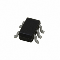
LMV841MG/NOPB National Semiconductor, LMV841MG/NOPB Datasheet - Page 14

LMV841MG/NOPB
Manufacturer Part Number
LMV841MG/NOPB
Description
IC OPAMP R-R I/O L-V L-P SC70-5
Manufacturer
National Semiconductor
Datasheet
1.LMV841MGNOPB.pdf
(22 pages)
Specifications of LMV841MG/NOPB
Amplifier Type
General Purpose
Number Of Circuits
1
Output Type
Rail-to-Rail
Slew Rate
2.5 V/µs
Gain Bandwidth Product
4.5MHz
Current - Input Bias
0.3pA
Voltage - Input Offset
50µV
Current - Supply
1.03mA
Current - Output / Channel
37mA
Voltage - Supply, Single/dual (±)
2.7 V ~ 12 V, ±1.35 V ~ 6 V
Operating Temperature
-40°C ~ 125°C
Mounting Type
Surface Mount
Package / Case
SC-70-5, SC-88A, SOT-323-5, SOT-353, 5-TSSOP
Lead Free Status / RoHS Status
Lead free / RoHS Compliant
-3db Bandwidth
-
Other names
LMV841MG
LMV841MGTR
LMV841MGTR
www.national.com
•
•
•
To calculate the noise voltage at the output of the op amp, the
first step is to determine a total equivalent noise source. This
requires the transformation of all noise sources to the same
reference node. A convenient choice for this node is the input
of the op amp circuit. The next step is to add all the noise
sources. The final step is to multiply the total equivalent input
voltage noise with the gain of the op amp configuration.
The input referred voltage noise of the op amp is already lo-
cated at the input, we can use the input referred voltage noise
without further transferring. The input referred current noise
needs to be converted to an input referred voltage noise. The
current noise is negligibly small, as long as the equivalent re-
sistance is not unrealistically large, so we can leave the
current noise out for these examples. That leaves us with the
noise sources of the resistors, being the thermal noise volt-
age. The influence of the resistors on the total noise can be
seen in the following examples, one with high resistor values
and one with low resistor values. Both examples describe an
op amp configuration with a gain of 101 which will give the
circuit a bandwidth of 44.5kHz. The op amp noise is the same
for both cases, i.e. an input referred noise voltage of 20nV/
To calculate the noise of the resistors in the feedback net-
work, the equivalent input referred noise resistance is need-
ed. For the example in
R
The voltage noise of the equivalent resistance can be calcu-
lated using the following equation:
eq
Input referred voltage noise of the op amp
Input referred current noise of the op amp
Noise sources of the resistors in the feedback network,
configuring the op amp
can be calculated using the following equation:
and a negligibly small input referred noise current.
FIGURE 3. Noise Circuit
Figure
3, this equivalent resistance
20168377
14
where:
The total equivalent input voltage noise is given by the equa-
tion:
where:
The final step is multiplying the total input voltage noise by the
noise gain, which is in this case the gain of the op amp con-
figuration:
The equivalent resistance for the first example with a resistor
R
equals:
Now the noise of the resistors can be calculated, yielding:
The total noise at the input of the op amp is:
For the first example, this input noise will, multiplied with the
noise gain, give a total output noise of:
In the second example, with a resistor R
sistor R
equals:
F
e
k = Boltzmann constant (1.38 x 10
T = absolute temperature (K)
R
e
e
R
nr
n in
nv
of 10MΩ and a resistor R
eq
eq
= thermal noise voltage of the equivalent resistor
= input voltage noise of the op amp
= resistance (Ω)
= total input equivalent voltage noise of the circuit
(V/
G
of 100Ω at 25°C (298K), the equivalent resistance
)
G
of 100kΩ at 25°C (298 K)
–23
J/K)
F
of 10kΩ and a re-


