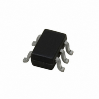
LMV841MG/NOPB National Semiconductor, LMV841MG/NOPB Datasheet - Page 16

LMV841MG/NOPB
Manufacturer Part Number
LMV841MG/NOPB
Description
IC OPAMP R-R I/O L-V L-P SC70-5
Manufacturer
National Semiconductor
Datasheet
1.LMV841MGNOPB.pdf
(22 pages)
Specifications of LMV841MG/NOPB
Amplifier Type
General Purpose
Number Of Circuits
1
Output Type
Rail-to-Rail
Slew Rate
2.5 V/µs
Gain Bandwidth Product
4.5MHz
Current - Input Bias
0.3pA
Voltage - Input Offset
50µV
Current - Supply
1.03mA
Current - Output / Channel
37mA
Voltage - Supply, Single/dual (±)
2.7 V ~ 12 V, ±1.35 V ~ 6 V
Operating Temperature
-40°C ~ 125°C
Mounting Type
Surface Mount
Package / Case
SC-70-5, SC-88A, SOT-323-5, SOT-353, 5-TSSOP
Lead Free Status / RoHS Status
Lead free / RoHS Compliant
-3db Bandwidth
-
Other names
LMV841MG
LMV841MGTR
LMV841MGTR
www.national.com
HIGH-SIDE CURRENT SENSING
The rail-to-rail input and the low V
LMV841/LMV842/LMV844 ideal op amps for high-side cur-
rent sensing applications.
To measure a current, a sense resistor is placed in series with
the load, as shown in
this sense resistor will result in a voltage drop, that is amplified
by the op amp.
Suppose it is necessary to measure a current between 0A and
2A using a sense resistor of 100mΩ, and convert it to an out-
put voltage of 0 to 5V. A current of 2A flowing through the load
and the sense resistor will result in a voltage of 200mV across
the sense resistor. The op amp will amplify this 200mV to fit
the current range to the output voltage range. Use the formu-
la:
to calculate the gain needed. For a load current of 2A and an
output voltage of 5V the gain would be V
If the feedback resistor, R
will be 4kΩ. The tolerance of the resistors has to be low to
obtain a good common-mode rejection.
HIGH IMPEDANCE SENSOR INTERFACE
With CMOS inputs, the LMV841/LMV842/LMV844 are par-
ticularly suited to be used as high impedance sensor inter-
faces.
Many sensors have high source impedances that may range
up to 10MΩ. The input bias current of an amplifier will load
the output of the sensor, and thus cause a voltage drop across
the source resistance, as shown in
is selected with a relatively high input bias current, this error
may be unacceptable.
The low input current of the LMV841/LMV842/LMV844 sig-
nificantly reduces such errors. The following examples show
the difference between a standard op amp input and the
CMOS input of the LMV841/LMV842/LMV844.
The voltage at the input of the op amp can be calculated with
For a standard op amp the input bias Ib can be 10nA. When
the sensor generates a signal of 1V (V
impedance is 10MΩ (R
be
V
FIGURE 6. High-Side Current Sensing
IN
= 1V - 10nA * 10MΩ = 1V - 0.1V = 0.9V
V
OUT
V
Figure
IN+
S
= R
), the signal at the op amp input will
= V
F
, is 100kΩ, then the value for R
F
/R
S
6. The current flowing through
G
- I
* V
B
Figure
* R
SENSE
OS
S
OUT
S
features make the
7. When an op amp
) and the sensors
/ V
SENSE
20168371
= 25.
G
16
For the CMOS input of the LMV841/LMV842/LMV844, which
has an input bias current of only 0.3pA, this would give
The conclusion is that a standard op amp, with its high input
bias current input, is not a good choice for use in impedance
sensor applications. The LMV841/LMV842/LMV844, in con-
trast, are much more suitable due to the low input bias current.
The error is negligibly small; therefore, the LMV841/LMV842/
LMV844 are a must for use with high impedance sensors.
THERMOCOUPLE AMPLIFIER
The following is a typical example for a thermocouple ampli-
fier application using an LMV841, LMV842, or LMV844. A
thermocouple senses a temperature and converts it into a
voltage. This signal is then amplified by the LMV841,
LMV842, or LMV844. An ADC can then convert the amplified
signal to a digital signal. For further processing the digital sig-
nal can be processed by a microprocessor, and can be used
to display or log the temperature, or the temperature data can
be used in a fabrication process.
Characteristics of a Thermocouple
A thermocouple is a junction of two different metals. These
metals produce a small voltage that increases with tempera-
ture.
The thermocouple used in this application is a K-type ther-
mocouple. A K-type thermocouple is a junction between Nick-
el-Chromium and Nickel-Aluminum. This is one of the most
commonly used thermocouples. There are several reasons
for using the K-type thermocouple. These include tempera-
ture range, the linearity, the sensitivity, and the cost.
A K-type thermocouple has a wide temperature range. The
range of this thermocouple is from approximately −200°C to
approximately 1200°C, as can be seen in
ers the generally used temperature ranges.
Over the main part of the range the behavior is linear. This is
important for converting the analog signal to a digital signal.
The K-type thermocouple has good sensitivity when com-
pared to many other types; the sensitivity is 41 uV/°C. Lower
sensitivity requires more gain and makes the application more
sensitive to noise.
In addition, a K-type thermocouple is not expensive, many
other thermocouples consist of more expensive materials or
are more difficult to produce.
V
FIGURE 7. High Impedance Sensor Interface
IN
= 1V – 0.3pA * 10MΩ = 1V - 3μV = 0.999997V
Figure
8. This cov-
20168352


