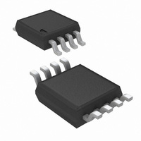
LMP7716MM/NOPB National Semiconductor, LMP7716MM/NOPB Datasheet - Page 16

LMP7716MM/NOPB
Manufacturer Part Number
LMP7716MM/NOPB
Description
IC AMP PREC R-R OUT DUAL 8-MSOP
Manufacturer
National Semiconductor
Series
LMP®, PowerWise®r
Datasheet
1.LMP7715MFNOPB.pdf
(18 pages)
Specifications of LMP7716MM/NOPB
Amplifier Type
General Purpose
Number Of Circuits
2
Output Type
Rail-to-Rail
Slew Rate
11.5 V/µs
Gain Bandwidth Product
17MHz
Current - Input Bias
0.1pA
Voltage - Input Offset
10µV
Current - Supply
1.3mA
Current - Output / Channel
66mA
Voltage - Supply, Single/dual (±)
1.8 V ~ 5.5 V
Operating Temperature
-40°C ~ 125°C
Mounting Type
Surface Mount
Package / Case
8-MSOP, Micro8™, 8-uMAX, 8-uSOP,
Lead Free Status / RoHS Status
Lead free / RoHS Compliant
-3db Bandwidth
-
Other names
LMP7716MM
LMP7716MMTR
LMP7716MMTR
Available stocks
Company
Part Number
Manufacturer
Quantity
Price
Company:
Part Number:
LMP7716MM/NOPB
Manufacturer:
TI
Quantity:
1 500
www.national.com
A feedback capacitance C
R
sponse. To achieve a maximally flat, 2
and C
Calculating C
pacitor values which are less than 2 pF. This is especially the
case for high speed applications. In these instances, it is often
more practical to use the circuit shown in
allow more sensible choices for C
pacitor, C
as R
SENSOR INTERFACE
The LMP7715/LMP7716/LMP7716Q have low input bias cur-
rent and low input referred noise, which make them ideal
choices for sensor interfaces such as thermopiles, Infra Red
(IR) thermometry, thermocouple amplifiers, and pH electrode
buffers.
Thermopiles generate voltage in response to receiving radi-
ation. These voltages are often only a few microvolts. As a
result, the operational amplifier used for this application
needs to have low offset voltage, low input voltage noise, and
low input bias current.
tion where the sensor detects radiation from a distance and
generates a voltage that is proportional to the intensity of the
radiation. The two resistors, R
vide high gain to amplify this signal, while C
frequency noise.
F
to maintain circuit stability and to control the frequency re-
A
FIGURE 7. Modified Transimpedance Amplifier
F
<< R
should be chosen by using
FIGURE 8. Thermopile Sensor Interface
F
′
, is (1+ R
F
.
F
from
B
Equation 3
/R
Figure 8
A
) C
F
F
is usually added in parallel with
. This relationship holds as long
A
shows a thermopile applica-
and R
can sometimes result in ca-
F
Equation 3
. The new feedback ca-
B
nd
, are selected to pro-
order response, R
Figure 7
F
removes the high
20183631
in order to
20183627
(3)
F
16
PRECISION RECTIFIER
Rectifiers are electrical circuits used for converting AC signals
to DC signals.
Each operational amplifier used in this circuit has a diode on
its output. This means for the diodes to conduct, the output of
the amplifier needs to be positive with respect to ground. If
V
tom amplifier will be positive. As a result, the diode on the
output of the bottom amplifier will conduct and the signal will
show at the output of the circuit. If V
cycle then the output of the top amplifier will be positive, re-
sulting in the diode on the output of the top amplifier conduct-
ing and delivering the signal from the amplifier's output to the
circuit's output.
For R
equation shown in
left open, no resistor needed, and R
ed.
IN
is in its positive half cycle then only the output of the bot-
2
/ R
1
≥
2, the resistor values can be found by using the
FIGURE 9. Precision Rectifier
Figure 9
Figure
shows a full-wave precision rectifier.
9. If R
2
/ R
4
1
IN
should simply be short-
= 1, then R
is in its negative half
3
should be
20183674


