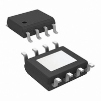
LME49724MR/NOPB National Semiconductor, LME49724MR/NOPB Datasheet - Page 16

LME49724MR/NOPB
Manufacturer Part Number
LME49724MR/NOPB
Description
IC AMP AUDIO MONO AB HIFI 8PSOP
Manufacturer
National Semiconductor
Datasheet
1.LME49724MRNOPB.pdf
(24 pages)
Specifications of LME49724MR/NOPB
Amplifier Type
Audio
Number Of Circuits
1
Output Type
Differential
Slew Rate
18 V/µs
Gain Bandwidth Product
50MHz
Current - Input Bias
60nA
Voltage - Input Offset
200µV
Current - Supply
10mA
Current - Output / Channel
80mA
Voltage - Supply, Single/dual (±)
5 V ~ 36 V, ±2.5 V ~ 18 V
Operating Temperature
-40°C ~ 85°C
Mounting Type
Surface Mount
Package / Case
8-PSOP
Lead Free Status / RoHS Status
Lead free / RoHS Compliant
-3db Bandwidth
-
www.national.com
* Value is application and converted dependent.
DISTORTION MEASUREMENTS
The vanishing low residual distortion produced by the
LME49724 is below the capabilities of commercially available
equipment. This makes distortion measurements more diffi-
cult than simply connecting a distortion meter to the
amplifier’s inputs and outputs. The solution, however, is quite
simple: an additional resistor. Adding this resistor extends the
resolution of the distortion measurement equipment.
The LME49724’s low residual distortion is an input referred
internal error. As shown in Figure 6, adding a resistor con-
nected between the amplifier’s inputs changes the amplifier’s
noise gain. The result is that the error signal (distortion) is
increased. Although the amplifier’s closed-loop gain is unal-
FIGURE 5. Typical Analog-to-Digital Converter Circuit
16
tered, the feedback available to correct distortion errors is
reduced, which means that measurement resolution increas-
es. To ensure minimum effects on distortion measurements,
keep the value of R
analyzer must be divided by a factor of (R
R
the device under test. The values used for the LME49724
measurements were R
This technique is verified by duplicating the measurements
with high closed-loop gain and/or making the measurements
at high frequencies. Doing so produces distortion compo-
nents that are within the measurement equipment’s capabili-
ties.
1
= R
2
and R
3
= R
4
5
, to get the actual measured distortion of
low. The distortion reading on the audio
1
, R
2
, R
3
, R
4
= 1kΩ and R
300442x7
3
+ R
4
5
)/R
= 20Ω.
5
, where


