LME49860NA/NOPB National Semiconductor, LME49860NA/NOPB Datasheet - Page 4
LME49860NA/NOPB
Manufacturer Part Number
LME49860NA/NOPB
Description
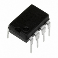
IC AMP AUDIO STER AB HIFI 8DIP
Manufacturer
National Semiconductor
Datasheet
1.LME49860MABD.pdf
(34 pages)
Specifications of LME49860NA/NOPB
Amplifier Type
Audio
Number Of Circuits
2
Slew Rate
20 V/µs
Gain Bandwidth Product
55MHz
Current - Input Bias
10nA
Voltage - Input Offset
140µV
Current - Supply
10.5mA
Current - Output / Channel
37mA
Voltage - Supply, Single/dual (±)
5 V ~ 44 V, ±2.5 V ~ 22 V
Operating Temperature
-40°C ~ 85°C
Mounting Type
Through Hole
Package / Case
8-DIP (0.300", 7.62mm)
Amplifier Class
AB
No. Of Channels
2
Supply Voltage Range
± 2.5V To ± 22V
Load Impedance
2kohm
Operating Temperature Range
-40°C To +85°C
Amplifier Case Style
DIP
No. Of Pins
8
Rohs Compliant
Yes
Number Of Channels
2
Voltage Gain Db
140 dB
Common Mode Rejection Ratio (min)
110 dB
Input Offset Voltage
0.7 mV at +/- 22 V
Maximum Operating Temperature
+ 85 C
Maximum Dual Supply Voltage
+/- 22 V
Minimum Operating Temperature
- 40 C
For Use With
LME49860NABD - BOARD EVALUATION LME49860NA
Lead Free Status / RoHS Status
Lead free / RoHS Compliant
Output Type
-
-3db Bandwidth
-
Lead Free Status / Rohs Status
Details
Other names
LME49860NA


www.national.com
CMRR
Z
A
V
I
I
R
C
I
OUT
OUT-CC
S
IN
VOL
OUTMAX
OUT
LOAD
Note 1: Absolute Maximum Ratings indicate limits beyond which damage to the device may occur.
Note 2: Operating Ratings indicate conditions for which the device is functional, but do not guarantee specific performance limits. For guaranteed specifications
and test conditions, see the Electrical Characteristics. The guaranteed specifications apply only for the test conditions listed. Some performance characteristics
may degrade when the device is not operated under the listed test conditions.
Note 3: Amplifier output connected to GND, any number of amplifiers within a package.
Note 4: Human body model, 100pF discharged through a 1.5kΩ resistor.
Note 5: Machine Model ESD test is covered by specification EIAJ IC-121-1981. A 200pF cap is charged to the specified voltage and then discharged directly into
the IC with no external series resistor (resistance of discharge path must be under 50Ω).
Note 6: Typical specifications are specified at +25ºC and represent the most likely parametric norm.
Note 7: Tested limits are guaranteed to National's AOQL (Average Outgoing Quality Level).
Note 8: PSRR is measured as follows: For V
Symbol
Common-Mode Rejection
Differential Input Impedance
Common Mode Input Impedance
Open Loop Voltage Gain
Maximum Output Voltage Swing
Output Current
Instantaneous Short Circuit Current
Output Impedance
Capacitive Load Drive Overshoot
Total Quiescent Current
Parameter
S
= ±22V, V
OS
is measured at two supply voltages, ±7V and ±22V. PSRR = | 20log(ΔV
V
-12V
V
-15V
–10V<Vcm<10V
V
–12V
V
–15V
R
R
R
R
f
Closed-Loop
Open-Loop
100pF
I
IN
OUT
S
S
S
S
L
L
L
L
R
R
R
R
R
R
V
V
V
V
V
V
V
V
V
V
= 10kHz
= 600Ω
= 2kΩ
= 10kΩ
= 600Ω
= ±18V
= ±22V
= ±18V
= ±22V
L
L
L
L
L
L
S
S
S
S
S
S
S
S
S
S
= 0mA
≤
≤
≤
≤
= 600Ω
= 2kΩ
= 10kΩ
= 600Ω
= 2kΩ
= 10kΩ
= ±18V
= ±22V
= ±18V
= ±22V
= ±18V
= ±22V
= ±20V
= ±22V
= ±18V
= ±22V
Vout
Vout
V
V
CM
CM
≤
≤
≤
≤
Conditions
4
12V
15V
12V
15V
(Note 6)
Typical
±16.7
±20.4
±17.0
±21.0
±17.1
±21.2
1000
0.01
10.2
10.5
120
120
140
140
140
140
140
140
±31
±37
+53
–42
30
13
16
LME49860
OS
(Note 7)
/ΔV
±19.0
Limit
110
125
±30
13
S
) |.
mA (max)
mA (min)
dB (min)
dB (min)
(Limits)
V (min)
Units
MΩ
mA
mA
mA
kΩ
dB
dB
dB
dB
dB
dB
%
Ω
V
V
V
V
V
Related parts for LME49860NA/NOPB
Image
Part Number
Description
Manufacturer
Datasheet
Request
R

Part Number:
Description:
National Semiconductor [8-Bit D/A Converter]
Manufacturer:
National Semiconductor
Datasheet:
Part Number:
Description:
National Semiconductor [Media Coprocessor]
Manufacturer:
National Semiconductor
Datasheet:
Part Number:
Description:
Digitally Controlled Tone and Volume Circuit with Stereo Audio Power Amplifier, Microphone Preamp Stage and National 3D Sound
Manufacturer:
National Semiconductor
Datasheet:
Part Number:
Description:
Digitally Controlled Tone and Volume Circuit with Stereo Audio Power Amplifier, Microphone Preamp Stage and National 3D Sound
Manufacturer:
National Semiconductor
Datasheet:
Part Number:
Description:
AC97 Rev 2 Codec with Sample Rate Conversion and National 3D Sound
Manufacturer:
National Semiconductor
Part Number:
Description:
Manufacturer:
National Semiconductor
Datasheet:
Part Number:
Description:
Manufacturer:
National Semiconductor
Datasheet:
Part Number:
Description:
General Purpose, Low Voltage, Low Power, Rail-to-Rail Output Operational Amplifiers
Manufacturer:
National Semiconductor
Datasheet:
Part Number:
Description:
8-bit 20 MSPS flash A/D converter.
Manufacturer:
National Semiconductor
Datasheet:
Part Number:
Description:
Low Noise Quad Operational Amplifier
Manufacturer:
National Semiconductor
Datasheet:
Part Number:
Description:
Quad Differential Line Receivers
Manufacturer:
National Semiconductor
Datasheet:
Part Number:
Description:
Quad High Speed Trapezoidal? Bus Transceiver
Manufacturer:
National Semiconductor
Datasheet:
Part Number:
Description:
Dual Line Receiver
Manufacturer:
National Semiconductor
Datasheet:
Part Number:
Description:
TTL to 10k ECL Level Translator with Latch
Manufacturer:
National Semiconductor
Datasheet: