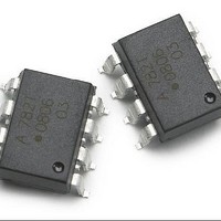
ACPL-782T-000E Avago Technologies US Inc., ACPL-782T-000E Datasheet

ACPL-782T-000E
Specifications of ACPL-782T-000E
Available stocks
Related parts for ACPL-782T-000E
ACPL-782T-000E Summary of contents
Page 1
... In a typical implementa- tion, and motor currents flow through an external resistor and the resulting analog voltage drop is sensed by the ACPL-782T. A differential output voltage is created on the other side of the ACPL-782T optical isolation barrier. This differential output voltage is proportional to the motor ...
Page 2
... Example: ACPL-782T-500E to order product of gullwing SMT DIP-8 package in Tape and Reel packaging with RoHS compliant. Option datasheets are available. Contact your Avago sales representative or authorized distributor for information. Package Outline Drawings ACPL-782T-000E Standard DIP Package 9.80 ± 0.25 (0.386 ± 0.010) 8 ...
Page 3
... Tolerances (unless otherwise specified): xx.xx = 0.01 Note: Floating lead protrusion is 0.5 mm (20 mils) max. Recommended Pb-Free IR Profile Recommended reflow condition as per JEDEC Standard, J-STD-020 (latest revision). Non-Halide Flux should be used. Regulatory Information The ACPL-782T-000E is approved by the following organizations 1577, component recognition program 3750 V RMS ...
Page 4
IEC 60747-5-5, DIN EN 60747-5-2(VDE 0884 Teil 2) Insulation Characteristics Description Installation classification per DIN VDE 0110/1.89, Table 1 for rated mains voltage 300 Vrms for rated mains voltage 450 Vrms for rated mains voltage 600 Vrms Climatic Classification Pollution ...
Page 5
Insulation and Safety Related Specifications Parameter Symbol Minimum External L(101) Air Gap (Clearance) Minimum External L(102) Tracking (Creepage) Minimum Internal Plastic Gap (Internal Clearance) Tracking Resistance CTI (Comparative Tracking Index) Isolation Group (DIN VDE0109) Absolute Maximum Ratings Parameter Storage Temperature ...
Page 6
DC Electrical Specifications Unless otherwise noted, all typical and figures are at the nominal operating conditions and T = 25°C; all Min. /Max. Specifications are within the Recommended Operating Conditions. A Parameter Symbol Input Offset ...
Page 7
AC Electrical Specifications Unless otherwise noted, all typicals and figures are at the nominal operating conditions and T = 25°C; all Min./Max. specifications are within the Recommended Operating Conditions. DD2 A Parameter Symbol V ...
Page 8
... V ) exhibits more than a 200 mV deviation from the average OUT- output voltage for more than 1Ps. The ACPL-782T will continue to function if more than 10 kV/Ps common mode slopes are applied, as long as the breakdown voltage limitations are observed. 15. Datasheet value is the differential amplitude of the transient at the ...
Page 9
... V DD1 1 2 ACPL-782T 0 Figure 1. Input Offset Voltage Test Circuit. 0.8 0.7 0.6 0.5 0.4 0.3 0.2 -55 - TEMPERATURE - °C A Figure 2. Input Offset Voltage vs. Temperature. 8.035 8.03 8.025 8.02 8.015 8.01 -55 -35 - TEMPERATURE - °C A Figure 4. Gain vs. Temperature +15 V DD2 0 0 AD624CD GAIN = 100 ...
Page 10
... V - SUPPLY VOLTAGE - V DD Figure 6. Gain vs. Supply. 0.005 0.004 0.003 0.002 4.5 4.75 5 SUPPLY VOLTAGE - V DD Figure 8. Nonlinearity vs. Supply DD2 8 0 ACPL-782T 0.47 PF 0.03 0.025 0.02 0.015 0.01 vs. V DD1 0.005 vs. V DD2 0 5.25 5.5 -55 Figure 7. Nonlinearity vs. Temperature. 4.2 3.4 2.6 1 ...
Page 11
V - INPUT VOLTAGE - V IN Figure 10. Supply Current vs. Input Voltage 100 1000 10000 FREQUENCY (Hz) Figure 12. Gain vs. Frequency. 5.5 ...
Page 12
... V DD1 1 0 ACPL-782T 0. IMPEDANCE LESS THAN Figure 15. Propagation Delay Test Circuits. 78L05 IN OUT 1 0.1 0 Figure 16. CMTI Test Circuits DD2 8 0 DD2 8 0 ACPL-782T 6 5 150 PULSE GEN + OUT + MC34081 0 150 pF + OUT MC34081 0 -15 V ...
Page 13
... RC anti-aliasing filter (R2 and C2). Although the application circuit is relatively simple, a few recommenda- tions should be followed to ensure optimal performance. The power supply for the ACPL -782T is most often obtained from the same supply used to power the power transis- tor gate drive circuit dedicated supply is required, in many cases it is possible to add an additional winding on an existing transformer ...
Page 14
... In addition, the layout of the PCB can also affect the isolation transient immunity (CMTI) of the ACPL-782T, due primarily to stray capacitive coupling between the input and the output circuits. To obtain optimal CMTI performance, the ...
Page 15
... ACPL-782T; this minimizes the loop area of the connection and reduces the possibility stray magnetic fields from interfering with the measured signal. If the sense resistor is not located on the same PC board as the ACPL-782T circuit, a tightly twisted pair of wires can accomplish the same thing. ...
Page 16
... If the same power supply is used both for the gate drive circuit and for the current sensing circuit very important that the connection from GND1 of the ACPL-782T to the sense resistor be the only return path for Note for the Voltage Divider: V (Line (Ra+Rb) ] <= 200 mV ...
Page 17
... Voltage sensing for DC rail measurement ACPL-782T is a suitable device to measure the DC rail voltage over different potentials rail voltage sensing application, the Line1 and Line2 in Figure 21 are the DC lines to be measured. Dividing ratio error due to the tolerances of the resistors From a differential calculation, the error in the voltage divider of Ra and Rb is expressed as 'A/A = Ra/(Ra + Rb) * ('Rb/Rb – ...
Page 18
... EMI issues R1//(R2+R3)=R1(R2+R3)/(R1+R2+R3) R2 and R3 divides the voltage across RL so that the voltage fed into ACPL-782T does not exceed +200 mV. The high impedance characteristic of the input terminals of ACPL- 782T helps in determining those resistors value since one can select relatively high resistance of R2 and R3 and R1 can be determined easily ...


