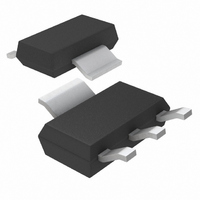
LT1117CST-3.3#PBF Linear Technology, LT1117CST-3.3#PBF Datasheet - Page 7

LT1117CST-3.3#PBF
Manufacturer Part Number
LT1117CST-3.3#PBF
Description
IC LDO REG FXD 3.3V 800MA SOT223
Manufacturer
Linear Technology
Datasheet
1.LT1117CM-3.3PBF.pdf
(16 pages)
Specifications of LT1117CST-3.3#PBF
Regulator Topology
Positive Fixed
Voltage - Output
3.3V
Voltage - Input
Up to 15V
Voltage - Dropout (typical)
1.1V @ 800mA
Number Of Regulators
1
Current - Limit (min)
800mA
Operating Temperature
0°C ~ 125°C
Mounting Type
Surface Mount
Package / Case
SOT-223 (3 leads + Tab), SC-73, TO-261
Primary Input Voltage
10V
Output Voltage Fixed
3.3V
Dropout Voltage Vdo
1.2V
No. Of Pins
3
Output Current
800mA
Operating Temperature Range
0°C To +125°C
Msl
MSL 1 - Unlimited
Rohs Compliant
Yes
Lead Free Status / RoHS Status
Lead free by exemption / RoHS Compliant
Current - Output
-
Available stocks
Company
Part Number
Manufacturer
Quantity
Price
APPLICATIONS INFORMATION
The LT1117 family of 3-terminal regulators are easy to
use. They are protected against short circuit and thermal
overloads. Thermal protection circuitry will shut down the
regulator should the junction temperature exceed 165°C
at the sense point. These regulators are pin compatible
with older 3-terminal adjustable regulators, offer lower
dropout voltage and more precise reference tolerance.
Reference stability over temperature is improved over
older types of regulators.
Stability
The LT1117 family of regulators requires an output
capacitor as part of the device frequency compensation.
A minimum of 10μF of tantalum or 50μF of aluminum
electrolytic is required. The ESR of the output capacitor
should be less than 0.5Ω. Surface mount tantalum
capacitors, which have very low ESR, are available from
several manufacturers.
When using the LT1117 adjustable device, the adjust
terminal can be bypassed to improve ripple rejection.
When the adjust terminal is bypassed, the required value
of the output capacitor increases. The device will require
an output capacitor of 22μF tantalum or 150μF aluminum
electrolytic when the adjust pin is bypassed.
Normally, capacitor values on the order of 100μF are
used in the output of many regulators to ensure good
load transient response with large load current changes.
Output capacitance can be increased without limit and
larger values of output capacitance further improve stability
and transient response.
Protection Diodes
In normal operation, the LT1117 family does not need any
protection diodes. Older adjustable regulators required
protection diodes between the adjust pin and the output
and between the output and input to prevent over stressing
the die. The internal current paths on the LT1117 adjust
pin are limited by internal resistors. Therefore, even with
capacitors on the adjust pin, no protection diode is needed
to ensure device safety under short-circuit conditions.
The adjust pin can be driven, on a transient basis, ± 25V with
respect to the output without any device degradation.
Diodes between input and output are not usually needed.
The internal diode between the output and input pins of
the device can withstand microsecond surge currents of
10A to 20A. Normal power supply cycling can not generate
currents of this magnitude. Only with extremely large output
capacitors, such as 1000μF and larger, and with the input
pin instantaneously shorted to ground can damage occur.
A crowbar circuit at the input of the LT1117 in combination
with a large output capacitor could generate currents large
enough to cause damage. In this case a diode from output
to input is recommended, as shown in Figure 1.
V
IN
IN
(OPTIONAL)
LT1117-3.3/LT1117-5
1N4002
LT1117
+
LT1117/LT1117-2.85
ADJ
D1
Figure 1
C
10μF
OUT
ADJ
R1
R2
+
C
150μF
OUT
1117 F01
V
OUT
1117fd
7


